Ronnie MogensenRonnie Mogensen
Department of Chemistry-Ångström Laboratory, Uppsala University, Box 538, SE-75121 Uppsala, Sweden
More by Ronnie Mogensen, Simon Colbin, Ashok Sreekumar Menon, Erik Björklund
, and Reza Younesi*
Cite this: ACS Appl. Energy Mater. 2020, 3, 5, 4974–4982
Publication Date:May 5, 2020
Abstract
Sodium-ion batteries based on all-naturally abundant elements, in which no cobalt, nickel, copper, and fluorine is used, can lead to a major breakthrough in making batteries more sustainable. Safety aspects—in particular, flammability of electrolytes—in the state-of-the-art battery technology is another important concern, especially for applications in which large numbers of cells are employed. Nonflammable battery electrolytes studied so far are based on highly fluorinated compounds or high salt concentrations, which suffer from high cost and toxicity. We here propose an electrolyte based on a single solvent and low-cost and fluorine-free salt at a lower range of “standard” concentrations. Our results show—for the first time—that sodium bis(oxalato)borate (NaBOB) is soluble in the nonflammable solvent trimethyl phosphate (TMP). This finding enables a nonflammable electrolyte with high ionic conductivity and promising electrochemical performance in full-cell sodium-ion batteries. An electrolyte of 0.5 M NaBOB in TMP provides an ionic conductivity of 5 mS cm–1 at room temperature, which is comparable to the commonly used electrolytes based on sodium hexafluorophosphate (NaPF6) and organic carbonate solvents. The proposed electrolyte shows a Coulombic efficiency of above 80% in the first cycle, which increased to about 97% from the second cycle in sodium-ion battery full-cells consisting of a hard carbon anode and a Prussian white cathode. This work opens up opportunities to design safe electrolytes which can further be optimized with electrolyte additives such as vinylene carbonate for industrial applications.
Introduction
ARTICLE SECTIONS
Sodium-ion batteries have been proposed to provide a more sustainable battery system compared to lithium-ion battery technology, facilitating the use of rechargeable high energy density batteries for large scale applications such stationary storage. (1−4) This is particularly achievable if cells contain only naturally abundant elements and by eliminating, among others, cobalt, nickel, and copper. Safety is another important concern for large scale applications, and in this respect, the flammability of the nonaqueous electrolytes may limit the use of the state-of-the-art battery technology in some applications. (5,6)
Most electrolytes used for sodium-ion batteries today are based on the same formula as the lithium-ion counterparts using organic carbonate solvents. (7) It should also be noted that the electrolyte composition is a concern for sustainability because the electrolytes used in both sodium- and lithium-ion batteries employ fluorinated salts such as sodium hexafluorophosphate (NaPF6) and sodium bis(trifluoromethanesulfonyl)imide (NaTFSI) which are toxic and expensive to produce. (3,8)
Here, we address both issues of the sustainability and safety of modern batteries by presenting a fluorine-free and nonflammable electrolyte for use in sodium-ion batteries. The proposed electrolyte is based on sodium bis(oxalato)borate (NaBOB) salt and trimethyl phosphate (TMP) as the sole solvent. Since its synthesis and characterization by Xu and Angell, (9) LiBOB has been used with great success in lithium-ion batteries, both as a stand-alone salt (10−15) and additive. (16−18) NaBOB, however, first synthesized by Zavalij et al. (19) in 2003, has been considered insoluble in organic solvents to be used in practice. Thus, salts such as sodium-difluoro(oxalato)borate (NaDFOB) (20) as well as other functionalized versions of NaBOB (21) have been developed to address this. In this work, we show the first example of a suitably conductive NaBOB-based electrolyte cycled in full-cell sodium-ion batteries with hard carbon anodes and Prussian white cathodes. The results are compared with NaPF6 in TMP electrolytes with and without additives.
TMP has previously been shown to reduce the flammability of electrolytes and therefore has been used as a cosolvent together with flammable solvents such as ethylene carbonate and propylene carbonate (PC). (22−25) TMP as a sole solvent suffers the major shortcoming of poor electrochemical stability, especially when using hard carbon anodes for sodium (24) or graphite anodes for lithium (26,27) because of insufficient anode passivation. This problem has been overcome in other studies by using highly concentrated electrolytes based on NaN(SO2F)2 (NaFSI), LiN(SO2F)2 (LiFSI), and LiN(SO2C2F5)2 (LiBETI) salts. (26−29) While highly concentrated electrolytes can combine good cyclability and safety, they do have some detrimental attributes such as low ionic conductivities, high viscosity, and furthermore, high cost due to the large quantity of fluorinated salts.
Here, we, for the first time, show that the combination of a relatively low concentration of NaBOB salt (0.5 M) with TMP provides remarkably stable cycling, demonstrating a very promising low-cost and green battery chemistry.
Results and Discussion
ARTICLE SECTIONS
“Structure, Conductivity, and Flammability”
The synthesis and structural properties of NaBOB has previously been investigated by Zavalij et al., (19) and their work provided a good foundation for the synthesis and determination of the purity of the NaBOB. LiBOB performance is sensitive to impurities, (17) and therefore, NaBOB was recrystallized in TMP in our work. Figure 1 shows X-ray diffraction, elemental analysis, and thermogravimetric analysis (TGA) of NaBOB salt synthesized in this work. The combined results from X-ray diffraction (XRD) and elemental analysis based on combustion analysis and inductively coupled plasma (ICP)–optical emission spectroscopy (OES) show that the salt has high purity as proven by the stoichiometry. No impurity phase was detected in the diffractogram (see Tables S1 supplemental for XRD analysis details). The TGA results indicate that NaBOB salt is stable up to 300 °C in nitrogen, which is an important advantage compared to NaPF6 being stable up to 140 °C under vacuum. (30)

Figure 2 shows that the ionic conductivity of NaBOB–TMP increases with NaBOB concentration, ultimately reaching 5 mS cm–1 for 0.5 M NaBOB in the TMP electrolyte at room temperature, which is similar to the corresponding ionic conductivity of 6 mS cm–1 for 1 M NaPF6 in TMP. These values are within the range of ionic conductivity of practical nonaqueous electrolytes based on carbonates. (31) The maximum concentration of NaBOB in TMP, that is 0.5 M, was achieved as a clear solution after both heating and rigorous stirring while a 0.6 M sample remained turbid after an identical treatment. This lower concentration of 0.5 M NaBOB compared to conventional electrolytes based on 1 M NaPF6 is in favor of reducing the electrolyte cost. In addition, the raw materials used for the synthesis of NaBOB are common and benign compared to the raw materials used in the production of the PF6– salts (32) such as HF, PCl5, and fluorine gas. Furthermore, the synthesis procedure for NaBOB is facile, safe, and does not require an inert environment.

Flammability tests were performed using a butane lighter in order to verify that the addition of NaBOB does not change the flammability properties of the TMP solvent. TMP did not ignite for any concentration of NaBOB (see Videos S1–S3 in the Supporting Information), while a reference sample consisting of PC showed a strong self-propagating flame. Immediately upon removal of the flame source from the NaBOB–TMP samples, all traces of fire disappeared, thus making it impossible to determine a self-extinguishing time. In contrast, PC burnt vigorously until entirely consumed using the same experimental setup (see Figure 3).

“Electrochemical Performance”
Cyclic voltammetry (CV) experiments in Figure 4a show that NaBOB undergoes reduction starting at 1.6 V versus Na+/Na in the first scan. However, as cycling progresses, effective passivation becomes evident as the reduction current significantly decreases. CV also shows oxidation current at 3 V in the first scan which can be decomposition of some reduction product during the first cycle. The stability however extends to approximately 4 V after the first cycle. Figure 4b displays CV of 1 M NaPF6 in TMP, where the reduction starts at 1 V in the first sweep, which is shifted to slightly lower voltages in subsequent sweeps (see Figure 4b, insert). The reduction current however increases in the following sweeps which suggests the formation of a poor passivation layer in 1 M NaPF6 in the TMP electrolyte.

The 0.5 M NaBOB in the TMP electrolyte was further evaluated in two-electrode sodium-ion full cells consisting of a hard carbon anode and a Prussian white cathode. The results in Figure 5a,b show that the NaBOB–TMP electrolyte provides superior cycling performance compared to the NaPF6–TMP electrolyte with Coulombic efficiency (CE) at 75% compared to that of 55% for NaPF6 for the first cycle. The additive-free NaBOB–TMP electrolyte enables stable cycling while the additive-free NaPF6–TMP, in accordance with the literature, (33) has very poor performance and only maintains 31 mAh g–1 at the 10th cycle compared to the 108 mA h g–1 of NaBOB–TMP. The SEI formation in the NaBOB-based electrolyte was observed between 1.5 and 2.5 V during the first charge, and the early NaBOB decomposition into carbonates stabilize the TMP solvent while NaPF6 clearly suffers from suboptimal passivation.

Figure 5c,d displays the voltage profile of hard carbon anode and the Prussian white cathode individually versus the reference electrode in a three-electrode cell. The reference electrode was also consisted of Prussian white, as an alternative to the unreliable Na metal electrode. (34) (Note that hard carbon half-cells became unstable when using sodium-metal counter electrodes which yielded no useful data. The PW half-cells using NaBOB–TMP suffered from high initial polarization while NaPF6–TMP suffered from rapid capacity fading which are likely due to parasitic reactions on the Na metal( see Figure S1 for the half-cell data). During the first charge, the reduction of NaBOB is clearly seen as a distinct plateau in the hard carbon potential during the initial stages (Figure 5c) that is absent from the NaPF6 counterpart (Figure 5d). These results are in agreement with the CV data shown in Figure 4 indicating active contribution of NaBOB in the formation of SEI on hard carbon, and it is in agreement with the previous studies on LiBOB showing relatively high onset reduction potential for LiBOB. (35)
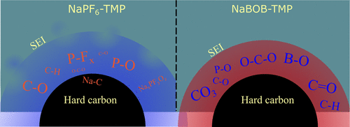
X-ray photoelectron spectroscopy (XPS) measurements were performed on hard carbon anodes after one full cycle in full-cells to compare the composition of SEI in the aforementioned electrolytes. Figure 6 displays the XPS spectra with peak assignments representing species present in the SEI on hard carbon and the relative atomic concentration. The C 1s spectrum of the pristine hard carbon sample contains two major peaks at 284.5 and 287 eV representing hard carbon and NaCMC binder. The C–C peak of hard carbon particles becomes almost invisible in the cycled electrodes, which indicates that the SEI formed on hard carbon is thicker than ∼10 nm (probing depth of in-house XPS with the Al Kα source). The C 1s and O 1s spectra of cycled electrodes reveal that the composition of SEI differs with the chemistry of the electrolyte; the SEI in the cell with NaBOB–TMP possesses hydrocarbons, C–O, and −CO3 species while being rich with C═O and/or O–C–O. (36) However, the SEI in the cell with NaPF6–TMP contains more C–O and P–O species. The C 1s spectrum of the cell with NaPF6–TMP also shows a small peak at a binding energy of ∼283 eV, indicating that the residual intercalated Na ions remained into the hard carbon framework even after full charge. (37) This peak is absent in the cell with NaBOB–TMP suggesting successful full desodiation of hard carbon at the end of the charge. The P 2p, F 1s, and B 1s spectra disclose that both NaBOB and NaPF6 salts as well as the TMP solvent contributed to SEI formation. The strong fluorine signal from NaPF6–TMP in the F 1s spectra shows that a part of phosphorus originates from NaPF6. However, TMP also participated in SEI formation as seen from the peak at 532 eV in the O 1s spectrum of the NaPF6–TMP sample, which is assigned to C–O–P and P═O species as there is no carbonate formed according to the C 1s spectrum. (38) The P 2p spectrum of hard carbon from the cell with NaBOB–TMP displays a small peak which is originated from TMP as there is no other source of phosphorus in this sample. All samples show one peak on Na 1s spectra, originated from the NaCMC binder and Na-containing SEI species.

The electrochemical test and surface analysis presented above clearly shows the active role of NaBOB compared to NaPF6 in electrolytes based on TMP in the formation of SEI on hard carbon. However, despite demonstrating benefits over the NaPF6-based electrolyte, the additive-free NaBOB–TMP still suffers from capacity fading and a relatively low CE of the first cycle (i.e. 75%) which needs to be improved. It has previously been shown that additives can be used to further improve the first cycle CE and cycling stability. (39−41) So, to test if the passivation of hard carbon could be improved in either system, we tested electrolytes containing both 5 and 10 vol % vinylene carbonate (VC) in galvanostatic cycling (see Figure 7).

The addition of 5 vol % VC to the NaBOB–TMP electrolyte increases the CE of the first cycle from 75 to 80%, while the cells with a higher additive amount of 10 vol % VC shows somewhat an erratic behavior (Figure 7a). All our replicate cells showed good repeatability except the NaBOB 10 vol % VC cells that showed considerable variation, with the first cycle CE values varying between 62 and 82%, suggesting that this is a more sensitive system than the other compositions. Figure 7c shows that the decomposition plateau of NaBOB gradually disappears with an increasing addition of VC, thus it appears that VC and NaBOB both participates in the SEI formation. The positive impact of VC becomes questionable at the higher 10 vol % VC loading, as sometimes a second feature close to 2.4 V appears which indicates excessive VC breakdown with detrimental effects on the cell reversibility.
VC is however essential for stability in the NaPF6–TMP electrolyte as the capacity fading is substantially suppressed in VC-containing cells in Figure 7b. The addition of VC to the NaPF6–TMP system leads to appearance of a new feature in the voltage curve at 1.6 V during charge (Figure 7d, insert). This feature looks quite similar for both 5 and 10 vol % albeit with a slightly quicker voltage increase for 10% VC. The effect of VC on the initial Coulombic efficiencies is dramatic as the CE of the first cycle increases from 56% without VC, to almost 84% for both electrolytes with 5% and 10 vol % VC. This indicates that the passivation of the hard carbon anode occurs by means of VC rather than NaPF6 or TMP. It also appears that the process is less sensitive to the concentration of VC than NaBOB–TMP as there no evidence of excessive additive decomposition even at 10 vol % VC. All of the best performing cells using VC with either NaBOB or NaPF6 display a rapid increase of the CE and reach above 96.5% CE by the second cycle, as shown in Figure 7e. Note that the error bar disclose the variation in CE obtained from identical cells.
Extended cycling for all compositions was performed up to cycle 50. However, the capacity for the cells with 1 M NaPF6 in TMP without VC additive fades rapidly because of the unstable cycling, and thus, these results are omitted. Both 5 and 10 vol % VC containing 1 M NaPF6 in TMP cells yield impressive cycling compared to their additive-free analogues (Figure 8a), confirming that VC continues to protect TMP against the hard carbon surface over time.

It appears that the long-term performance in the 0.5 M NaBOB electrolytes also gains a long-term performance boost by addition of VC, even if the improvement is not as dramatic as for NaPF6. Based on the results, a VC-based or at least a VC-containing passivation layer is preferable to the SEI formed by NaBOB alone as the 0.5 M NaBOB cells using 5 vol % VC loading consistently show improved long-term capacity retention. It should be mentioned that the cell with 0.5 M NaBOB in the TMP electrolyte with 10 vol % VC often showed worse performance than the baseline additive-free electrolyte even though only the best performing cell is shown in Figure 8 with very impressive results (see Figure S2 in the Supporting Information for the results from all cells). These cycling performance in full cells is almost similar to our previous result on half-cells based Prussian white cathodes using 1.5 M NaPF6 in dimethoxyethane. (42)
NaBOB salt is without doubt superior NaPF6 salt when used in TMP without additives; however, when additive-free NaBOB is compared to electrolytes that use VC, it is generally true that the additive-free electrolyte loses more sodium inventory during the first cycle and suffers slightly lower CE in later cycles (see Figure 8).
The best performing cells of both TMP–NaBOB and TMP–NaPF6 using 5 and 10 vol % VC all have CE values between 98.5 and 99% after 10 cycles, while additive-free TMP–NaBOB cycles above 97.5% CE in cycles 4–50. Although longer cycling is required to reveal if the SEI is truly stable, the electrolytes tested here represent an important step toward practically viable nonflammable sodium-ion batteries.
Conclusions
The use of NaBOB as the electrolyte salt in sodium-ion batteries is for the first time shown here. A nonflammable and fluorine-free electrolyte based on NaBOB dissolved in TMP disclosed promising results in terms of the electrolyte ionic conductivity (5 mS cm–1 at room temperature) and electrochemical performance in sodium-ion full cells. Previous publications used high concentrations of salt or highly fluorinated solvents/additives to achieve high CE on hard carbon anodes. However, we have instead shown that 0.5 M NaBOB in TMP enables relatively high CE in hard carbon-based full-cell sodium-ion cells. The proposed electrolyte can of course be further optimized using electrolyte additives to achieve higher initial CEs and an improved cycle life. As one example, VC has here been shown to improve the electrochemical performance of full-cell sodium batteries using the studied electrolyte compositions. Overall, this means that high energy-density cells (>250 W h kg–1 based on active materials) built from low-cost and abundant materials can be cycled at Columbic efficiencies above 99%. This is in cells with electrolytes that cannot burn using a solvent that freezes at a low −46 °C, without the environmental and health aspects of using highly fluorinated compounds. In short, this work is a promising step to remove most of the problems that state-of-the-art electrolytes suffer from.
Experimental Section
ARTICLE SECTIONS
Materials
TMP (99%) was purchased from Merck and was produced by Acros. TMP was dried over freshly activated molecular sieves before use in electrolytes. NaBOB was synthesized using the method stated by Zavalij et al. (19) with the added step of recrystallizing the synthesized NaBOB in TMP before vacuum drying at 100 °C for more than 12 h to make sure that the salt was sufficiently dry for use in an electrolyte. The resulting salt was characterized by X-ray diffraction and elemental analysis. VC was obtained from Gotion Inc. and used as received. Hard carbon anode powder was obtained from a commercial source and used as received while Altris AB supplied the Prussian white (NaxFe[Fe(CN)6]) (x > 1.8) cathode powder.
Analytical Methods
Elemental analysis was performed by Medac LTD., and two equivalent samples were analyzed twice each using CHN combustion analysis & ICP–OES (see supplemental for full report). Conductivity was performed using a Mettler Toledo SevenGo Duo pro pH/ORP/Ion/Conductivity meter SG78 with an InLab 738ISM probe under argon in a glove box (O2, H2O 1 ppm). Thermogravimetric analysis was performed on a TA Instruments TGA Q500 under nitrogen flow between room temperature and 600 °C with 5 °C min–1 heat rate. Powder X-ray diffraction measurements were performed in the transmission mode on a Stoe & Cie GmbH Stadi X-ray powder diffractometer equipped with a Ge monochromator (single-wavelength Cu Kα1). A Mythen 1 K Si strip detector was operated in the sweeping mode with an angular resolution of 2θ = 0.015°. Full details of the Rietveld refinement are available in the Supporting Information.
Electrolyte Preparation
NaBOB–TMP mixtures with the concentrations 0.1, 0.2, 0.3, 0.4, 0.5, and 0.6 mol L–1 were prepared in volumetric flasks. The solutions of 0.3, 0.4, 0.5 M, and above required heating (∼60 °C) to dissolve, while 0.6 M solution remained turbid even after heating. The preparation and heating were performed under argon in a glove box using a heater/stirrer hotplate.
Flammability Test
The flammability tests were performed on electrolytes by soaking a strip of glass fiber in the electrolyte and exposing it to a butane gas flame in a fume hood. The tests were recorded using a mobile phone camera, and pictures and times were collected from the recordings.
Electrode Preparation and Cell Assembly
For Prussian white cathodes, the active material, super C65 (C·NERGY) carbon additive, and NaCMC binder (Sigma-Aldrich) were mixed in a 85:10:5 ratio by weight, respectively, and to this, approximately 5 mL distilled water per gram of active material was added before mixing for 1 h in a planetary ball mill. The slurry was coated using an applicator rod with 150 μm gap onto a 20 μm carbon-coated aluminum foil. Hard carbon anodes were also prepared on a carbon-coated aluminum foil using a 95:5 ratio by weight of hard carbon and the NaCMC binder with approximately 6 mL distilled water per gram of active material before mixing for 1 h using a planetary ball mill and coating with a 100 μm gap applicator rod. The anodes and cathodes were both punched into 20 mm in diameter discs with a mass loading of approximately 1.9 mg cm–2 for PW and 1.1 mg cm–2 for hard carbon electrodes. The electrodes were dried at 140 °C under vacuum overnight. The cells for galvanostatic cycling used 30 mm diameter Dreamweaver gold (polyaramid fiber) separators and 100 μL electrolyte, while the half-cells, three-electrode cells, and cells for cyclic voltammetry used 30 mm diameter Whatman glass-fiber separators and 200 μL electrolyte. All types were assembled in pouch-cells that were sealed at 2 mbar vacuum. All cell assembly and electrode drying were performed in an argon glove box with O2 and H2O <1 ppm.
Electrochemical Methods
Galvanostatic cycling for two-electrode cells was performed at 30 mA g–1 (corresponding to 60 μA cm–2) between 1 and 3.8 V on a Neware BTS4000 galvanostat while three-electrode cells were cycled on a Biologic MPG2 potentiostat between 1 and 4 V.
Cyclic voltammetry was performed on a Biologic MPG2 potentiostat. The measurements were performed in pouch cells with two-electrode cells using a metallic sodium (Aldrich 99.9%) counter electrode or three-electrode cells with a Prussian white counter electrode and a Prussian white reference electrode desodiated to 3.3 V versus Na+/Na. Both cell types used a carbon-coated aluminum foil working electrodes, and scans were performed using 1 mV s–1 scan speed. Scans started at OCV and were performed between 0 and 4.5 V versus Na+/Na.
XPS Characterization
XPS measurements of cycled electrodes were carried out using a PerkinElmer PHI 5500 system with an excitation photon energy of 1486.6 eV. The samples were prepared in an Ar-filled glove box, where cycled cells were opened and rinsed with TMP. Thereafter, the washed samples were gently dried under vacuum over night before being mounted on a sample plate and sealed in a transfer cup. This made it possible to transfer the samples into the XPS without air exposure. The hard carbon electrodes were energy calibrated against the carbon black peak set to 284.4 when visible and secondary carbon peaks when the substrate peak was obscured.
【Article link】
https://doi.org/10.1021/acsaem.0c00522

