Program in Nano Science and Technology, Graduate School of Convergence Science and Technology, Seoul National University, 1 Gwanak-ro, Gwanak-gu, Seoul 08826, Republic of Korea
More by Yong Jun Gong, Hyunjin Kim, Gayeong Yoo, Jinil Cho, Seonmi Pyo, Yong Hyun Cho, Jeeyoung Yoo, and Youn Sang Kim
Cite this: ACS Appl. Energy Mater. 2019, 2, 11, 8310–8318
Publication Date:October 30, 2019
Abstract
Li metal is an ideal anode material for batteries based on Li ion because of its high theoretical specific capacity and low redox potential. However, the repeated formation and collapse of solid electrolyte interphase layer on its surface results in poor cycling performance leadable short lifetime and safety issues. To solve these problems, we introduced a bilayer consisting of a Ni/polymer composite electrolyte (NPCE). A Li|Li symmetrical cell system with an NPCE showed a superior stability tolerable voltage range of ±15 mV during 1000 cycles even at a high current density of 20 mA cm–2. Additionally, the NPCE-applied Li metal batteries (LMB) maintained the specific capacity of 85.16% after 500 cycles at a high current density rate of 5C; meanwhile, the specific capacity of an LMB, which used a conventional polyolefin separator, faded to 52.34%. Thus, the NPCE is an excellent gel polymer electrolyte for stable SEI layer control on the Li surface during cycling.
1. Introduction
Li metal is the most promising anode material for next-generation LIBs as a replacement for conventional carbon-based anodes because of its high theoretical specific capacity of 3862 mAh g–1 and the lowest redox potential of −3.04 V (vs H). (1−3) However, there are several obstacles that must be addressed before Li metal can be used in LIBs, such as life span and safety issues. (1,4,5) These drawbacks stem from the formation of a solid electrolyte interphase (SEI) layer at the surface of the Li metal anode (LMA). (1,4) Unlike the conventional graphite anodes, LMA utilize a lithiation-delithiation mechanism known as “hostless” electrochemical plating/stripping to charge and discharge. (6) Through this lithiation-delithiation process, the LMA undergoes the repeated formation and collapse of an unstable SEI layer between the electrolyte and Li metal surface. (1,4,6) Thus, the surface of the LMA is continuously exposed to an undesirable interfacial reaction, resulting in severe side effects correlated with capacity fading and decreased lifetimes of LIB, limitless volume expansion of Li metal anode, continuous consumption of fresh electrolyte, and isolated Li induced from dendritic growth. Therefore, additional treatments of the surface of the LMA based on studies of interfacial phenomena are indeed an indispensable process to stabilize LMA for application to LIBs. (6,7) To address these issues, many researchers have developed diverse approaches. (8−13) Among these methods, in terms of dimensional aspects, introducing an interlayer (e.g., metal mesh, fibrous metal felt, and 3D porous structure) between the LMA and the separator has shown excellent results and the potential to overcome problematic issues, achieving a stable SEI layer. (14−19) The introduction of an interlayer helps the SEI layer to grow not on the surface of LMA but on the conductive interlayer stably, and the applied structure, which has well-distributed frame structure, induces the Li+ ion flux to be dispersed homogeneously, so that LMA no longer suffers from the undesirable interfacial phenomena. (15,16,20) Our previous work had also shown that a conductive interlayer can improve the stability of LMA. (20) Moreover, the use of an interlayer is advantageous in allowing the existing Li metal foil to be used as it is without having additional treatment to the reactive surface of the LMA or preparing different structure of LMA for interfacial stability. Considering that, we explored the Ni/polymer composite electrolyte (NPCE) as a gel-type polymer electrolyte to solve the interfacial issues of LMA. To the best of our knowledge, gel polymer electrolyte system composed of “metal-within-polymer” is the first effort to control the SEI layer at the LMA interface by manipulating the structure of the electrolyte. Ni is a representative metal with low reduction potential compared to other metals, and has good mechanical strength. Also, Ni is chemically stable under strong reductive condition like the required voltage levels during the SEI formation. Therefore, when NPCE was applied as a gel polymer electrolyte on a LMA, the Ni-particle-embedded part acted as a framework to support the growth of a stable SEI layer. In a Li|Li symmetrical cell with NPCE, the voltage differences are maintained within very low levels of ±4 and ±15 mV, respectively, even at corresponding high current densities of 10 and 20 mA cm–2 up to 1000 cycles, indicating a significant improvement of the surface stability of the LMA without any additional treatment. Furthermore, when the NPCE is introduced, electrolyte was retained at a nearly 10 times higher amount than in a conventional Polypropylene (PP) separator during the process of repeated formation and collapse of the SEI layer. In a test of Li metal batteries (LMB) with the NPCE applied, the capacity was 85.16% of the initial value after 500 cycles at a 5C rate, which is significantly higher than the rate of 52.34% from an LMB test using conventional PP. In addition, because the NPCE is based on a flexible polymer, it can be made into pouch cells easily because of its good formability, which allows twisting of the material. This indicates that the NPCE is suitable for the conventional LIB manufacturing process and that it can replace the conventional separator and gel polymer electrolyte. NPCE can dramatically enhance the stability of LIBs and LMB without any structural change in LMA and any additional treatments.
2. Experimental Section
The NPCE was fabricated using a Mayer rod as described in Additional Information 1 and Figure S1. The pore distribution of the first layer is shown in Figure S2. The electron conductivity of the Ni-particle-embedded layer as 3D conductive framework and the insulation of the PVdF-HFP layer as separator was confirmed by measuring the sheer resistance (Ni-particle-facing side, 1.7729 Ω cm–2; PVdF-HFP-facing-side, insulated). (21) The electron conductivity of the Ni-particle side of the NPCE was confirmed to be maintained even when the shape of the NPCE was changed (Figure S3). To identify the role of Ni microparticles in the NPCE, we also prepared pristine PVdF-HFP without Ni microparticles as a reference with the same dimensions.
3. Results and Discussion
3.1. Expected Mechanism of the NPCE
Figures 1a–d show the plating/stripping process of a general LMA following the mechanism. The SEI layers are formed between the Li metal surface and the electrolyte due to the strong reductive condition which arises during the plating step. (20,22) In a conventional carbon-based anode, the SEI layer serves as a passivation layer for passing Li+ ions to prevent fresh electrolyte consumption by reduction. For a LMA, the SEI layer forms according to the same mechanism in the carbon-based anode. (20,22) However, plating/stripping induces a volume change of the LMA, and SEI layer cracking occurs on the surface because of the brittle nature of the SEI layer during the repeated plating/stripping process. (20,22) These cracks cause the fresh Li metal source to be exposed to the electrolyte and create new SEI layers while the electrolyte is consumed, leaving an irregular surface with a nonuniform SEI layer. This undesirable behavior of the Li metal surface continues until the cell no longer operates. The fluctuating surface of the LMA also leads to Li+ ion flux at the tip of the surface, causing the growth of Li dendrites. The Li metal surface then collapses and cannot maintain an expanded structure, and part of the Li metal is surrounded by the SEI layer and becomes isolated. (20,22) This “isolated Li” does not participate in the reaction and accumulates as a resistive element on the Li metal surface, degrading the cycle characteristics of the LMA during cycling. (23) In addition, the dendritic growth reaches extreme levels (Figure 1e) and causes internal short circuits. However, when the NPCE is applied, a conductive Ni-particle-facing side is in contact with the LMA. In the plating condition, the electrons can migrate from the underlying LMA to the upper Ni particles. This structure also induces homogeneous Li+ ion flux by well-dispersed Ni particles, unlike the situation where Li+ ion flux can be biased by a nonfully flat Li metal surface. With the Ni particles first in contact with the Li+ ion flux to form a SEI layer on the Ni-particle-facing side, an unstable SEI layer no longer forms on the surface of the LMA. In the subsequent stripping process, the structure of the SEI layer formed on the Ni-particle-facing side is stably maintained even when the Li+ ions diffuse out from the Li metal source. Hence, the surface of the LMA does not deform because of the unstable SEI layer (Figures 1f −i). The expected mechanism of the NPCE, shown in Figure 1j, was supported by a half-cell test, a Li|Li symmetrical cell test and by surface analyses (SEM and XPS) results.

3.2. Galvanostatic Cycling Measurements in a Symmetrical Cell Test
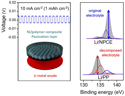
The symmetrical cell test, which is a useful method for assessing the surface stability of LMA through galvanostatic polarization with continuous plating/stripping, was conducted to evaluate the cycling stability. (16) Before the symmetrical cell test, the assessment of SEI layer was performed with the half-cell structure (Additional Information 2). In a symmetrical cell test, the current densities of 1/5/10/20 mA cm–2 were applied to confirm the stability of the symmetrical cells. Controlling the growth of SEI layer at currents higher than 0.5 mA cm–2 is an obstacle associated with LMAs, and many studies have reported the stability of LMAs through symmetrical cell evaluations based on current density levels of 1–10 mA cm–2 at the standard of 1 mAh cm–2 (Table S1). (18) Thus, we performed symmetrical cell tests with current densities of 1/5/10/20 mA cm–2 on the 1 mAh cm–2 scale, with an additional extreme test performed at 10 mA cm–1 (10 mAh cm–1). When current is applied, the symmetrical cell exhibited the stepwise behavior. A description of each step is given in Additional Information 3. At a normal current density of 1 mA cm–2, the cell test was first performed for 500 cycles. The PP symmetrical cell shows the increment in the voltage difference within initial 50 cycles, as shown in Figure 2a. In a conventional PP case, in which a new SEI layer is formed in every cycle, irregular anodic polarization and voltage overshoot occur because of the resistance generated by the repeated formation and collapse of the SEI layer in addition to the diffusion resistance. This inactive component increases the resistance, causing the voltage hysteresis to increase due to the ohmic potential drop. Li+ ions have to pass through the thick SEI layer covered by inactive component, which inducesan overpotential in the anodic polarization to appear at the beginning of the plating/stripping process. In contrast, the NPCE symmetrical cell did not show nonuniform resistive behavior caused by continuous SEI layer formation because the SEI layer of the NPCE symmetrical cell is stable. Of course, similar behavior with PP was observed at a low current density of 0.1 mA cm–2 (1 mAh cm–2) in the NPCE symmetrical cell (Figure S4). Ohmic polarization is not dominant at low current, and thus anodic polarization can be observed better in low current. Judging by these result, the SEI layer of the NPCE symmetrical cell is expected to be thinly formed and they are also very stable. Therefore, the voltage of the NPCE symmetrical cell maintained a voltage difference of ±4 mV during 500 cycles; this case was assumed to generate fewer inactive components than that in the PP symmetrical cells because a stable SEI layer on the Ni-particle-facing side protects the LMA and keeps the diffusion rate unaffected. So, in NPCE symmetrical, anodic polarization curve shows relatively flat behavior because there are few elements caused by a decomposition issue of electrolyte component. In case of 5 mA cm–2, unlike the NPCE symmetrical cell have voltage difference ranging from ±4 to 5 mV, the PP symmetrical cell exhibited a voltage range increment from the initial cycle and cell failure occurred within 226 cycles, as demonstrated in Figure 2b and Figure S5a. The analogous results were observed for the PVdF-HFP applied symmetrical cell as a reference in Figure S5b. The PVdF-HFP has been used in many research as an efficient gel polymer electrolyte system that has advantages such as reasonable ionic conductivity and relatively wide electrochemical window, to be applied to LIBs. (24) As this reason, the PVdF-HFP electrolyte indicates less voltage difference increment in the initial state. Still, the cell fails eventually because the PVdF-HFP used is only just a thicker polymer electrolyte containing more liquid electrolyte without Ni-particle-embedded layer so their interfacial reaction mechanism is same as PP separator. To understand the stability of the LMA with NPCE more clearly, we conducted the same test under an even harsher condition with a higher current density of 10 and 20 mA cm–2 with the cells cycled 500 times. Prior to cycling test, electrochemical impedance spectroscopy (EIS) was carried out to evaluate the SEI layer formation at the initial stage (Figure S6). At the symmetrical cell test of 10 mA cm–2 and 20 mA cm–2 for 500 cycles, the PP symmetrical cell failed at the initial stage. Especially at 20 mA cm–2, the PP separator burned out due to Joule heating induced by the inactive component (Figure S7). This phenomenon also occurred in the PVdF-HFP case without Ni microparticles. However, at 10 and 20 mA cm–2 with the NPCE symmetrical cell, the voltage difference showed stable behavior in the range of ±5 and ±15 mV, respectively, as shown in Figure 2c, d. Figure 2e shows the voltage hysteresis of the NPCE symmetrical cells for high current density of 5/10/20 mA cm–2. Depending on the current density, their voltage increase remains at a low level compared to those of the PP and PVdF-HFP symmetrical cells (Figure S5). We conducted additional tests on the symmetrical cells to confirm the persistence of the effect of NPCE on the surface of the LMA. After a one-week rest, the NPCE symmetrical cell test was restarted to verify the resting time effects. During another 500 cycles, the voltage increased because of the scarce accumulation of the inactive component on the surface, and the tendency of the voltage hysteresis was saturated given that the NPCE symmetrical cell was extremely stable (Figure S8). As shown in Figure 2f, g, under the severe test condition of 10 mAh cm–2 (10 mA cm–2), the PP symmetrical cell and the PVdF-HFP symmetrical cell failed within five cycles. Meanwhile, the Li/NPCE case maintained stable operation up to 100 cycles. In addition, the long-term experiments up to 2500 cycles at current density of 5 mA cm–2 (1 mAh cm–2) showed stable behavior (Figure S9). These results confirm the surface stability of the LMA, suggesting that a LMA with an NPCE does not undergo the uncontrollable surface problem stemming from the repeated formation and collapse of undesirable additional SEI layers. Hence, the NPCE can very effectively form a stable SEI layer at a high current rate (C rate), making it very useful for batteries that use Li metal as the anode.

3.3. SEM Image Analysis
Scanning electron microscopy (SEM) images were analyzed to visualize the stability effect of the NPCE on the surface of LMA. The surfaces of Li metal with symmetrical cells with PP applied and NPCE applied were analyzed as the worst and the best one, respectively. The before and after images of surface state at 10 mA cm–2 (1 mAh cm–2) of the Li metal and Ni-particle-facing side of NPCE are shown in Figure 3. Figure 3a shows a SEM surface image and an optical image (inset picture) of pure Li metal before cycling and Figure 3b presents a SEM sectional image. The surface of the Li metal was flat before the plating/stripping cycles. Figures 3c and 3d are facial and cross-sectional images of Li metal with the PP symmetrical cell after a high current density test at 10 mA cm–2 for 128 cycles. Although the LMA using PP underwent far fewer cycles (128 cycles) at 10 mA cm–2 than in the NPCE case (500 cycles), an inactive layer accumulated on the surface of the Li metal, and an area of mossy Li deposits where dendritic growth can continue also appeared on the surface of this anode (Figure 3c). The cross-sectional image also shows that the volume of the Li metal increased significantly comparing the initial state and that the structural instability escalated because of the continuous volume change (Figure 3d). This is a typical result of the formation and collapse of unstable SEI layers on the surface of LMA. However, the Li metal of the symmetrical cell with the NPCE applied showed a surface similar to that with the pure Li metal without significant deformation induced by electrolyte decomposition with the formation of an inactive layer, as described in Figure 3e. Despite the hundreds of repeated cycles at the high current density of 10 mA cm–2, the Li metal maintained a smooth surface. The passivation effect of NPCE with regard to the obvious structural fracture of the SEI layer can be observed in the sectional image (Figure 3f). These results indicate that the NPCE served as a stable protective layer for the LMA and that the NPCE enhanced the cycle stability of the LMA effectively. On the other hand, a comparison of the Ni-particle-facing side of NPCE before and after the test proves that the Li+ ions penetrated into and plated the void areas of the Ni-particle-embedded polymer matrix through the SEI layer between the PVdF-HFP part and the Ni-particle-embedded part (Figures 3g, h). During the lithiation-delithiation process on the surface of the LMA, a SEI layer was formed stably on the Ni-particle-embedded layer. When Li+ ions are plated, Li+ ions penetrate through the SEI layer and are deposited into the voids in the Ni structure; thus, a stable SEI layer is maintained without fractures.

3.4. XPS Measurement
The X-ray photoelectron spectrometer (XPS) spectrum of the surface of a LMA to a depth of about 20 nm is shown in Figure 4. The XPS analysis was carried out with the 10 mA cm–2 samples in an ultrahigh vacuum, and the results correspond to the SEM images. Figure 4a shows the XPS spectra of the three Li cases of a pure Li metal foil as reference, a Li electrode with a cycled PP symmetrical cell (cycled Li/PP) as the worst one and a Li electrode with a cycled NPCE symmetrical cell (cycled Li/NPCE) as the best one, respectively. In the cycled Li/PP case, the Li 1s peak was distinguished by two subpeaks as one peak, which is the same peak found in the pure Li metal foil (Li 1s, 55.20 eV), along with another discernible secondary peak (Li 1s′, 55.80 eV), which cannot be considered as pure Li, as shown in Figure 4b. Because Li metal has the lowest sensitivity factor (0.0057, take off angle 53°) in the XPS spectrum, this secondary Li 1s′ peak distinguished from the pure Li metal foil is considered to stem from the different putative decomposition materials, in this case, LiF, LixOy, LiOH, Li2CO3, and LixPOy, which were induced by the residue of the SEI layer as inactive materials. (25−28) When Li/NPCE was cycled, the Li 1s peak also was divided into two subpeaks. The major peak was a Li 1s peak from Li metal, while the other weak peak was a Li 1s′ peak from the residue of the SEI layer, as in the case of the cycled Li/PP shown in Figure 4c. However, the intensity of the minor peak of Li 1s′ was lower than that of the cycled Li/PP. XPS mapping images also showed that in the Li/PP case, the thickness of the surface was greater (3.40) than that of another (2.62) case due to the considerable amount of residue of the SEI layer, and the surface, furthermore, had a nonuniform distribution and lower intensity of the Li element, as shown in Figure S10a. However, when NPCE was applied, the thickness of the surface was as thin as 77% in the PP case, and the distribution of the Li element was more uniform with high intensity, as shown in Figure S10b. Though the thickness of the surface of the Li/NPCE case was not dramatically different from that of the Li/PP case, the materials constituting the surfaces differed unequivocally considering the difference in the XPS peaks of phosphorus. Phosphorus was the central atom of the anion of the LiPF6 electrolyte, which causes the cell to have ion conductivity between the electrode. Moreover, the high ratio of electrolyte remaining suggests that the electrolyte is no longer consumed to generate a new SEI layer. The degradation of the constituents of the electrolyte deteriorates the ion transport property and can adversely affect the cell in many respects. (28) Therefore, the stable presence of the electrolyte is very important for maintaining the characteristics of the cell, and measuring the binding state of phosphorus in the electrolyte is an indirect yet definite means of determining the characteristics of the cell. Figure 4d shows the XPS spectra of phosphorus. In the Li/PP case, a considerable portion of phosphorus was present in a different form (phosphate, 134.21 eV; LixPOyFz, 135.05 eV; LixPFy, 137.03 eV) from that of the electrolyte (LiPF6, 137.87 eV) added during the manufacturing process, and the components of the electrolyte were in a state of significant dissipation (Figure 4e). (29−33) In other words, the results indicated that pure Li as an anode material was subject to unwanted side reactions with the fresh electrolyte for lithiation–delithiation and consequentially that the pure electrolyte material was decomposed into a nonactive form (phosphate, 59.34%; LixPOyFz, 27.35%; LixPFy, 3.51%), possibly becoming a resistive component, relative to the primary form (LiPF6, 9.80%). On the other hand, when NPCE was applied, different forms (phosphate, LixPOyFz, LixPFy) were noted, which had been generated as a result of side reactions that rarely appeared despite running even more cycles. This indicates that a large percentage of the electrolyte (LiPF6) remained in the original form, as shown in Figure 4f. In the Li/NPCE case, phosphorus existed in small quantities in the inactive materials (phosphate, 6.96%; LixPOyFz, 5.04%; LixPFy, 20.38%) and remained mainly in the form of an electrolyte (LiPF6, 67.60%) (Figure 4d). When the XPS mapping image of phosphorus was compared to that of Li, the dispersion and intensity of the points in the two mapping images showed a similar tendency, as presented in Figure S10c, d. Although many more cycles had progressed, when the electrolyte was decomposed, the initial state of the decomposition material (LixPFy) mainly existed through reaction 1; small amounts of the decomposition materials (LixPOyFz) proceeding from reaction 2 were detected. (34) Therefore, considering the results of the XPS analyses of Li/PP and Li/NPCE, the long-cycle stability of Li/NPCE shows that the Ni-particle side of the NPCE helps the LMA to remain stable. These results can be attributed to the NPCE resolving the interfacial problems of the LMA.

(1)

(2)Figure 4g, h show the XPS spectra of oxygen and phosphorus on the Ni-particle side of NPCE before and after cycling, respectively. O did not appear because the electrolyte was removed for the XPS analysis. In Figure 4i, after cycling, the Ni-particle side of NPCE shows pure Li and the SEI layer components in the XPS spectra, identical to the surface of the Li metal. This is consistent with the results showing that Li+ ions undergo plating/stripping on the Ni-particle-embedded layer though the SEI layer, similar to the proposed mechanism shown in Figure 1. Figure 4j shows that in addition to the peaks of phosphorus that have already appeared in Li metal, there are other peaks that can be regarded as nickel phosphorus oxide (phosphate, 134.21 eV; LixPOyFz, 135.05 eV; nickel phosphorus oxide, 136.22 eV; LixPFy, 137.03 eV; LiPF6, 137.87 eV). (35,36) The peak generated on the surfaces of the Ni-particle side of NPCE after cycling is predicted to be that of a nickel phosphorus oxide (NixPyOz) composite, in which Ni reacts with phosphorus and oxygen derived from the electrolyte in strong reductive conditions (Figure S11). NixPyOz is expected as a component of the SEI layer induced from the reduction of the Ni microparticles and the electrolyte. The composed NixPyOz chemical is expected as a stable phase, which does not react as an active species during cycling and keeps the SEI layer stable, unlike without the NPCE. On the basis of this observation, the SEI layer is composed of Li-based phosphorus oxide salts, including nickel phosphorus oxide (phosphate, 31.45%; LixPOyFz, 27.75%; nickel phosphorus oxide, 22.60%; LixPFy, 15.65%; LiPF6,2.55%). Therefore, for the LMA with an NPCE, electrons from the Li metal move through the Ni microparticles that are in contact with Li to form a stable SEI layer including the nickel phosphorus oxide between the Ni microparticles, and these passivation layers allow Li+ ions to be plated and stripped without deforming the SEI layer. Of course, the uncontrollable interfacial reaction scarcely occurs on the surface of the Li metal during the long cycle time. Additionally, a Ni peak was not observed in the XPS wide scan, providing direct and simple proof that the PVdF-HFP-tightened Ni microparticles do not escape despite the fact that PVdF-HFP existed only at 10 wt % in the Ni-particle-embedded layer (Figure S12).

3.5. Galvanostatic Cycling Measurements in Li Metal Battery Test
Galvanostatic cycling measurements of an LMB with LiFePO4 (LFP) were taken to determine the effectiveness of the NPCE in practical LMB systems. First, the testing at a low current density (0.2C/0.5C/1C/5C/10C/0.2C) was performed (Figure S13) and subsequently, the tests of the cycling performance and CE outcomes were carried out at a current density of a 5C rate after one precycle at 0.1C from 2.5 to 4.2 V. As shown in Figure 5a, the LMB with an NPCE has superior cycling performance compared to that of a conventional LMB with PP. After 500 cycles, the LMB with NPCE maintained a specific capacity of 78.95 mAh g–2, reaching 85.16% of the initial specific capacity, whereas the LMB with PP showed a specific capacity of only 48.25 mAh g–2, 52.34% of the initial specific capacity. This 85.16% is an excellent value, because the industrial standard of LIB cycle life evaluation is 80% or more of remaining capacity after 500 cycles at a 0.5C rate. In addition, the LMB with an NPCE showed a high CE, exceeding 99.99% even at the 500th cycle (Figure 5b). In comparison with a conventional LMB (CE, 97.72% at the 500th cycle), cells with NPCE outperformed in terms of the CE, especially considering the capacity fading outcomes, and LMB cells using an NPCE were superior to those with PP in terms of reliability. The side phenomena that occurred at the surface of the LMA were suppressed with the NPCE as the LMA was safely protected. Thus, the Li//NPCE//LFP cell also maintained the characteristics of an LMA. Such consequences appear to be possible because the function of the NPCE remained for a long time even under harsh high-current-density conditions. Additionally, the soft property of the NPCE was utilized in a flexible pouch cell (Figure S14). The flexibility of the NPCE allows pouch cells in a bending state without any difficulty, and flexibility is expected to be readily applicable to existing cell production processes without any special modifications. These results of Li//NPCE//LFP cell tests demonstrate that the NPCE has a significant role in ensuring a reliable LMB system, and the soft property of the NPCE indicates the possibility of its immediate applicability to existing battery manufacturing systems.

4. Conclusion
In this work, we introduced a Ni/polymer composite electrolyte, NPCE, which was applied to Li metal batteries. NPCE was designed with a stacked layer of Ni microparticles embedded in a polymer matrix of PVdF-HFP and with a layer of neat PVdF-HFP. NPCE was manufactured by a simple casting method, demonstrating excellent formability given that the PVdF-HFP held the metal microparticles tightly and the Ni microparticles were not dispersed during cycling. A closely packed Ni-particle-embedded layer induced stable SEI layer formation on the surface of Ni particles and allowed the LMA to operate safely. Thus, the NPCE boosted the reliability of the LMB system. A NPCE half-cell showed that the SEI layer maintained a stable structure owing to the Ni 3D structure. In the symmetric cell configuration, the NPCE-applied cell operated successfully up to 1000 cycles at a high current density of 20 mA cm–2 without any additional manipulations or additives, and the surface of the LMA was kept clean as compared to that of a conventional cell with PP. Because NPCE can effectively stabilize the surfaces of LMA via a stable SEI layer which includes nickel phosphorus oxide composite on the surface of the Ni particles, the electrolyte component in the NPCE symmetrical cell remained at a level of 10-fold that in a PP symmetrical cell after cycling and did not electrochemically decompose. Moreover, the specific capacity of Li//NPCE//LFP remained at 85.16% of the initial specific capacity after 500 cycles at a 5C rate, whereas the specific capacity of an LMB that used a conventional polyolefin separator faded to 52.34%. NPCE is an excellent gel polymer electrolyte for stable SEI layer control on the Li surface during cycling, and it prevents the decomposition of the electrolyte component. Hence, the stability at a high C rate and the reliability of the cells were dramatically enhanced. NPCE is a new and efficient system that suggests the possibility of introducing metal to electrolyte for high-capacity batteries using Li metal as the anode material even though it still has room for improvement in thickness, and it is expected to inspire researchers who study LMBs.
【Article link】
https://doi.org/10.1021/acsaem.9b01788

