Department of Polymer Science, University of Akron 170 University Circle, Akron, Ohio 44325, United States
More by Wenfeng Liang, Yunfan Shao, Yu-Ming Chen, and Yu Zhu*
Cite this: ACS Appl. Energy Mater. 2018, 1, 11, 6064–6071
Publication Date:November 1, 2018
Abstract
A highly conductive and electrochemically stable dual-salt solid polymer electrolyte (SPE) for a high-capacity cathode was developed. A phase-diagram approach was adopted to provide rational guidance for achieving a high ionic conductivity (over 1.76 mS/cm at 30 °C). The synergy of combining different salts rendered superior electrochemical stability to the SPE with an electrochemical window from 0 to 5 V (vs Li+/Li) in linear sweep voltammetry and up to 4.15 V in lithium metal batteries (LMBs). The SPE exhibited outstanding long-term stability performance in lithium plating/stripping experiments under current densities from 0.08 to 0.5 mA/cm2. The solid-state lithium metal batteries (with an LiNi0.8Co0.15Al0.05O2, NCA, cathode) exhibited initial capacities of 165 mAh/g at a rate of 0.1 C and 113 mAh/g at a rate of 1 C at 30 °C. The average Coulombic efficiency of solid-state batteries was over 99.99% in the first 1000 cycles at a rate of 1 C, and the capacity retention was 66% after 1000 cycles. In addition, the per cycle capacity fading after the initial 100 cycles was only 0.017%/cycle. The results demonstrate that the SPE is a promising candidate electrolyte for a high-energy-density solid-state lithium metal battery.
1. Introduction
Since the commercialization of lithium ion batteries (LIBs) in 1990s, (1) rechargeable lithium batteries have become the most attractive battery technology, used widely in portable electronics and recently being implemented in electrical vehicles and large-scale grid-energy storage systems. (2−6) However, the low power and energy density of current LIB electrodes and potential safety concerns regarding the flammable organic solvent based electrolytes hinder the further utilization of LIBs in many emerging applications. (7,8) Extensive research has been conducted to develop superior alternative electrode materials to improve the energy density of LIBs. (9−12) Among those new materials, a lithium metal anode is the holy grail for future lithium batteries due to the high theoretical specific capacity (3860 mAh/g), the low redox potential (−3.04 V vs standard hydrogen electrode), and the low mass density (0.56 g/cm3). (13) However, despite substantial efforts toward developing lithium metal batteries (LMBs), their practical applications have remained stagnant due to several challenges. First, the flammable organic liquid electrolyte is a potential safety issue, which would be particularly severe with the failure of a lithium metal anode based battery. Second, the uneven lithium plating/stripping process on the lithium metal electrode would result in uncontrollable dendritic growth, which may penetrate the separator and cause an internal short circuit, leading to battery thermal runaway. (14−16) Finally, the unstable solid electrolyte interphase formation on the lithium metal anode could continuously consume the electrolyte and lithium source in the battery, resulting in a decrease in Coulombic efficiency and an increase in cell impedance. (17,18) As such, the implementation of a lithium metal anode in current lithium ion batteries to replace the graphite anode is essential to enhance energy density but challenging. In addition, the successful implementation of a lithium metal anode also serves as a basis for many techniques beyond lithium ion batteries such as a lithium–sulfur battery and a lithium–oxygen battery. (19,20)
The implementation of a lithium metal anode requires nonflammable, dendrite-mitigated, and electrochemically stable electrolyte. One straightforward way is to use a solid electrolyte with a strong shear modulus, where the lithium dendrite formation could be mitigated and even completely suppressed. (21) In order to achieve comparable performance in the battery, it is necessary to design a solid-state electrolyte with a high ionic conductivity that is compatible with commercial cathodes. Solid polymer electrolytes (SPEs) have emerged as candidates for solid-state lithium metal batteries due to their low cost and flexible nature. The most investigated polymer electrolyte, poly(ethylene oxide) (PEO) and alkali metal salt composite, has been extensively studied since 1970s. (22,23) In addition to PEO, many other polymers, for instance, poly(ethylenimine) (PEI), (24) poly(acrylonitrile) (PAN), (25) poly(vinylidene fluoride) (PVDF). (26) and poly(methyl methacrylate) (PMMA), (27) have also been investigated. Up until now, PEO has remained arguably the best polymer host due to its outstanding solvability with lithium salts and high efficiency in the coordination with lithium ions. (28,29) The drawback of the PEO is that it exhibits a low ionic conductivity at room temperature (∼10–3 to 10–2 mS/cm) and shows a relatively low lithium ion transference number (tLi+) of around 0.2–0.5. (30−32) While organic liquid plasticizers, such as ethylene carbonate (EC) and dimethyl carbonate (DMC), could be used to enhance the ionic conductivity in PEO by decreasing its crystallinity, these small organic molecules adversely affect the physical properties of the SPE and decrease the thermal stability of SPE. (33) Previously, it was reported that plastic crystal materials, such as succinonitrile (SN), could effectively increase the ionic conductivity in a PEO-based SPE system as an alternative solid plasticizer. Conductive SPE with added SN has been demonstrated and showed good performance with acceptable mechanical strength. (34,35) However, most SPE systems were tested in lithium ion batteries with lithium iron phosphate (LFP) as the cathode due to the limited potential range of the PEO electrolyte in the cell (<4.0 V). Therefore, an SPE with a wider electrochemical window that enables the utilization of more advanced 4 V cathodes such as LiNi0.8Co0.15Al0.05O2 (NCA), LiNixCoxMnxO2 (NMC), and LiCoO2 (LCO) is required.
Herein, a dual-salt-based solid polymer electrolyte has been developed. The SPE was prepared by mixing lithium bis(oxalate)borate (LiBOB) and lithium bis(trifluoromethanesulphonyl)imide salt (LiTFSI) together with the solid plasticizer succinonitrile (SN) in poly(ethylene glycol) diacrylate (PEGDA). The freestanding SPE film was prepared by cross-linking the SPE precursor through UV curing. Guided by a ternary phase diagram analysis, we achieved the composition of a dual-salt SPE with high ionic conductivity at 30 °C. Thermal and electrochemical characterizations were carried out to determine the stability of the SPE. Lithium metal batteries with Li|SPE|NCA assembly were fabricated and tested. The results indicated that the dual-salt SPE had outstanding stability with a 4 V cathode.
2. Results and Discussion
2.1. Synthesis of Solid Polymer Electrolyte
The most challenging task for developing an SPE is to achieve high ionic conductivity. Two mechanisms have been developed to explain the Li+ migration in the solid polymer matrix. (36) In the amorphous region of a polymer matrix, the lithium ions and counteranions dissociate and then the lithium ions could hop from one coordination site to another adjacent coordination site. Such repetitive hopping and coordination with adjacent coordinate sites is driven by the motion of amorphous polymer chains. (37) However, in the crystalline region of a polymer matrix, lithium ions move by hopping over spiral channels, which are created by the folding of crystalline polymer chains. In the PEO-based polymer electrolyte system, lithium ion migration is believed to occur by the formation and disruption of coordination bonds between lithium ions and ether groups. Therefore, the fast segmental relaxation will improve ionic conductivity. (38,39) In this scenario, in order to achieve the optimized ionic conductivity, it is necessary to determine the amorphous region composition in the polymer electrolyte. For this purpose, a ternary phase diagram of cross-linked PEGDA/lithium salt/plasticizer was constructed with assistance from polarized optical microscopy image characterization, shown in Figure 1a. In this experiment, samples with different ratios of PEGDA, SN, and lithium salts were prepared and then cast on a glass slide and cured under UV light to form the SPE film. The phase diagram should be measured at different temperatures to simulate the broad operating temperatures of different battery applications. Following the general understanding of an SPE, the amorphous region of the phase diagram at high temperature should be larger than that at low temperature. The phase diagrams of an SPE at −10, 25, and 70 °C were studied. As shown in Figure 1a, at −10 °C, the large isotropic region, represented by blue dots, can be identified in the triangular phase diagram. The amorphous region of the polymer matrix could be ascribed to the hindrance of crystallization by the cross-linked polymer network and plasticization effects of solid SN. The polarized optical microscopy image of the amorphous composite region was completely dark, as shown in Figure 1b. The polymer crystallization region was observed when the concentration of PEGDA was nearly 100%, as represented by green dots. The clear crystal structure was found in the corresponding polarized microscopy image in Figure 1c. On the other hand, when the percentage of polymer content was low in the composites, the freestanding SPE membrane could not be formed even after cross-linking. Instead, a gel-like electrolyte was obtained (indicated by orange dots). In addition, a phase separation was observed when the concentrations of lithium salt or plasticizer (shown as purple and red dots, respectively) were high in the composite. Overall, on the basis of the result of the ternary phase diagram of cross-linked PEGDA/lithium salt/plasticizer, a feasible working region was determined, represented by the blue shadow region in the triangular phase diagram. The ternary phase diagrams of composites at 25 and 70 °C are shown in the Supporting Information (Figure S1). It is clear that the amorphous regions at 25 and 70 °C were larger. However, the battery application requires a wide operating temperature range; thus, an optimized composition was further investigated on the basis of the ternary phase diagram at −10 °C. Figure 1d–f shows photos of the deformability test of freestanding SPE membranes, prepared by photo-cross-linking of the ternary polymer precursor with the composition within the amorphous region. As illustrated in Figure 1d–f, the transparent SPE membranes are flexible and twistable so that they can be used as ionic conducting films in battery fabrication to replace the liquid electrolyte and separator.

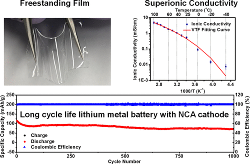
The ionic conductivity and lithium ion transference number are regarded as the two most important parameters for an SPE. On the basis of the ternary phase diagram, the ionic conductivity of materials with selected ratios from the amorphous region was measured at 30 °C. The conductivity gradient is plotted in the phase diagram, shown in Figure 2a. The optimized ionic conductivities were reached at the ratios of 20:50:30 (cross-linked PEGDA:plasticizer:lithium salt) and 25:40:35, where the average values are 0.76 and 0.72 mS/cm, respectively. The highest ionic conductivity measured in an individual sample reached 1.76 mS/cm at 30 °C. The SPEs with optimized compositions were used in the following experiments.

The temperature-dependent ionic conductivity for an SPE (cross-linked PEGDA:plasticizer:lithium salt = 25:40:35) was also investigated as shown in Figure 2b. With an increase in the temperature, the polymer chain mobility would increase, leading to higher ionic conductivity. The average ionic conductivity of the SPE is 0.72 mS/cm at 30 °C. As the temperature was increased to 100 °C, the ionic conductivity increased to 4.77 mS/cm. The conductivity dropped to 0.091 mS/cm when the temperature was 0 °C. The Vogel–Tammann–Fulcher model empirical formula was used to perform the curve fitting (as plotted by a red line in Figure 2b). (40) The activation energy of the SPE is 7.23 kJ/mol, and other fitting results are shown in Table S1. The lithium ion transference number, tLi+, was obtained by using the potentiostatic polarization method and electrochemical impedance measurements. (30,41,42)Figure S2 demonstrates the polarization curve and the ac impedances. Further details about the transference number calculation are shown in the Supporting Information. The calculated tLi+ value is approximately 0.535, which is higher than that of the conventional liquid electrolyte (usually less than 0.5), due to the entrapment of the large anions of LiTFSI by the polymer network. (43)
The thermal properties of the SPE were evaluated by thermogravimetric analysis (TGA) and differential scanning calorimetry (DSC). As shown by the TGA results (Figure 2c), the cross-linked SPE is thermally stable over 100 °C, pointed out by a dashed line in Figure 2c. The weight loss of the SPE matches well with the component ratio in the composite. The weight loss of the SPE was compared with those of a gel electrolyte and liquid electrolyte in the literature (Figure S8). The results indicate that the polymer electrolyte in this work performs like a solid-state electrolyte. Figure 2d shows the DSC results of the cross-linked SPE film. With the plasticizer, the DSC curve shows a flat line without obvious peaks, demonstrating the amorphous state of the SPE.
2.2. Electrochemical Tests of Solid Polymer Electrolyte
For LMBs with high-potential cathodes (>4 V vs Li+/Li), a large, stable electrochemical window is essential. Most reported SPE systems have used LiTFSI as the lithium salt due to the high ion dissociation ratio. In this work, an additional salt, LiBOB, was added to the SPE (with the LiTFSI:LiBOB molar ratio 1:0.085) to improve the electrochemical stability. Previously, LiBOB was reported to improve electrochemical stability in a liquid electrolyte based battery. (44) We therefore expected to achieve a higher electrochemical stability with additional LiBOB added to the SPE system. A recent exploration also indicated that the LiTFSI:LiBOB has a synergetic effect for stabilizing LFP cathode based LMBs. (45) In this work, the LiTFSI:LiBOB molar ratio is determined by the maximum solubility of LiBOB in the SPE system. A linear sweeping voltammetry (LSV) test was carried out to determine the electrochemical working potential range (Figure 3a). The dual-salt SPE exhibits a stable potential window up to 5.0 V vs Li+/Li. The CV result is shown in Figure 3b. The peaks between 0.4 and −0.5 V (vs Li+/Li) correspond to the lithium plating and stripping processes. From the CV results, the SPE is stable up to 4.8 V (vs. Li+/Li) without showing any obvious oxidation peaks and remains unchanged after several cycles. As comparison, single-salt (LiTFSI) SPE films were also prepared and tested in LSV and CV experiments. The results are shown in Figure S3. These confirmed that LiBOB could help stabilize the SPE, accommodate the serious deterioration at a higher potential range, and hence, improve the electrochemical compatibility with high-potential cathodes.

To further investigate the electrochemical stability of a Li metal anode in the SPE battery system, a symmetrical Li|SPE|Li cell was fabricated and subsequently implemented for plating/stripping tests. As shown in Figure 3c, the cell was tested at a current density of 0.1 mA/cm2 for a period of 1.5 h for each half-cycle. During the charge/discharge process, lithium ions were plated/stripped on the Li metal anode surface, which would increase the surface roughness and lead to the formation of dendrites. Figure 3c represents the time-dependent potential profile of the symmetrical cell cycled over 2300 h at 30 °C. Parts d and e of Figure 3 are the enlarged views of Figure 3c, showing the beginning and ending parts of the test, respectively. In Figure 3c, a slight increase in the overpotential at the beginning was observed, which could be ascribed to the SEI layer formation. Then in the following cycles, the potential decreased and became increasingly stable. The plating/stripping experiments were also conducted at current densities of 0.5 mA/cm2 (6 min per half-cycle, 15 min per half-cycle, and 20 min per half-cycle) and 0.08 mA/cm2 (1.5 h per half-cycle), shown in Figure S4. The cells showed stable potential profiles up to 1700 h (0.5 mA/cm2, 6 min per half-cycle) and 3000 h (0.08 mA/cm2, 1.5 h per half-cycle) respectively. Even with extended stripping/plating time (15 min per half-cycle and 20 min per half-cycle at 0.5 mA/cm2), the initial test indicated that the SPE could be cycled for more than 100 h. All of these results exhibited an exceptional long-term cycling performance of the dual-salt SPE system with a Li metal anode.
Since the stability of the dual-salt SPE/Li metal anode interface is an essential parameter for the long-term stability of rechargeable lithium metal batteries, electrochemical impedance spectroscopy (EIS) was used to analyze the interfacial property. In this experiment, symmetric Li|SPE|Li cells were examined and EIS was measured over time under 30 °C (Figure 3f). Figure 3g reports the corresponding charge transfer resistance (Rct) and bulk resistance (Rb) evolution over time. The results were obtained by using the equivalent circuit, and detailed parameters are reported in Table S2 in the Supporting Information. The Nyquist plot showed that the semicircle expanded over time, indicating an increased charge transfer resistance. After 20 days, Rct remained stable, which as confirmed in Figure 3g. This resistance could be related to the formation of the passivation layer on the Li metal anode surface. (46,47) However, Rb was very small and remained almost unchanged from the beginning. This is consistent with a previous report that the value of Rb will be very small when the conductivity of the SPE is above 0.1 mS/cm. (48) On the basis of the EIS data, a stable SPE with a passivation layer on the interface of the Li metal anode was formed to prevent the electrolyte from further deterioration. This phenomenon suggested that the SPE is compatible with the Li metal anode for a safer operation in rechargeable Li metal batteries.
2.3. Lithium Metal Batteries with Solid Polymer Electrolyte
The contact between the porous electrode and the SPE is the key factor determining the cell performance of SPE-based LMBs. To enhance the contact between the cathode and the SPE film, the cathode was coated with the SPE precursor and then rested overnight before the freestanding SPE film (250–500 μm) was laminated and cross-linked. The cross-section SEM images of SPE with cathode are shown in Figure S5. The SEM shows that the interface between the cathode and the SPE is smooth and that a flexible SPE is conformally coated on the porous cathode. The 4 V cathode LiNi0.8Co0.15Al0.05O2 (NCA), which was recently used in state of the art lithium ion batteries for electrical vehicle applications, (8,49) replacing lithium iron phosphate (LFP), was used in this research. Most reported solid polymer electrolyte work has focused on an LFP-based cell due to the limited electrochemical window of the SPE. (50,51) To the best of our understanding, a long cycling life of an LMB with an NCA cathode and SPE has not been demonstrated. The NCA-based LMBs with the Li|SPE|NCA configuration were fabricated in this work and tested. The cells were first charged and discharged at an electrochemical window of 2.5–3.9 V (vs. Li+/Li) for the initial cycles to achieve stable Coulombic efficiency, an then the cells were cycled between 2.5 and 4.15 V (vs Li+/Li) in the following cycles. Figure 4a demonstrates the capacities of NCA batteries at different current densities with 10 cycles per stage. The battery exhibited reversible specific capacities of about 156, 137, 116, 102, 89, 77, and 142 mAh/g at corresponding current densities of 0.1, 0.2, 0.4, 0.6, 0.8, 1, and 0.1 C (based on 1 C = 180 mAh/g). Figure 4b shows the corresponding charge/discharge profile in the rate tests. Further long-term cycle performance testing was also conducted using the same NCA cells. The SPE-based batteries were tested at 0.1 C for 500 cycles and at 1 C for 1000 cycles. The cycling results are shown in Figure 4c,d, respectively. The corresponding charge/discharge profiles are reported in Figure 4e,f. At 0.1 C (Figure 4c), the battery exhibited an initial specific capacity of ∼165 mAh/g. The average Coulombic efficiency was over 99.78% for 500 cycles. The capacity retention after 100 cycles was 77%, and the final retention was 48% after 500 cycles. At 1 C (Figure 4d), the initial specific capacity of the cell was 113 mAh/g. The capacity retentions after 100, 500, and 1000 cycles were 77%, 72%, and 66%, respectively. The average Coulombic efficiency was over 99.99% for 1000 cycles. It is worth mentioning that the capacity fading after the initial 100 cycles was very slow, with only 0.017%/cycle capacity fading in the rest of the 900 cycles. This indicates that the SPE-based LMB is very stable once the initial passivation layer is successfully formed on the lithium metal anode. Additional tests for 0.2 C were also conducted (Figure S6a). The initial specific capacity was ∼152 mAh/g with a ∼45% retention on its 500th cycle. The average Coulombic efficiency of the battery was ∼99.85%.

For comparison, a single-salt (LiTFSI) SPE battery was tested as well (Figure S6c). As shown in the Supporting Information, the capacity fading of the single-salt SPE was very fast, with nearly no capacity remaining after just 100 cycles. This result is coherent with previous reports, where a single salt was applied in PEO, showing a rapid capacity fading at an electrochemical window of over 4 V. (52)Table S3 gives previous reports of an NCA cathode based LMB, including in solid-state battery and liquid electrolyte based cells. The dual-salt SPE LMBs reported in this work demonstrated long cycling stability similar to those of the liquid electrolyte-based batteries and were significantly better than previously reported solid state batteries. (52,53) The results showed that the dual-salt SPE has a great potential to build up long cycling life LMBs with a high specific capacity 4 V cathode.
3. Conclusions
In conclusion, a solid-state, highly conductive dual-salt polymer electrolyte was successfully designed and tested for lithium metal batteries with a 4 V cathode. The freestanding SPE film was prepared by cross-linking the SPE precursor through UV-initiated polymerization. A ternary phase diagram analysis was used to guide the SPE design to reach the ideal ionic conductivity. An SPE with ionic conductivity of over 1.76 mS/cm (at 30 °C) was achieved. A dual-salt system (LiTFSI and LiBOB) was used to enhance the electrochemical stability of the SPE. The system exhibited a wide electrochemical window of up to 4.8 V (vs Li+/Li) in LSV and CV and up to 4.15 V in lithium metal battery cells. The SPE was able to effectively suppress lithium dendrites, as indicated in lithium plating/stripping tests at 30 °C. The SPE film remained stable for over 2300 h with a current density of 0.1 mA/cm2 and for over 1700 h at current density of 0.5 mA/cm2. The dual-salt SPE-based batteries delivered an initial capacity of 165 mAh/g at 0.1 C and 113 mAh/g at 1 C. The long cycling test of the SPE-based LMB at 1 C under 30 °C exhibited outstanding stability with an average Coulombic efficiency of over 99.99% and capacity retention of over 77% after 100 cycles, 72% after 500 cycles, and 66% after 1000 cycles. This work demonstrates a solid-state battery with a stable SPE system that can achieve high conductivity at room temperature, a wide electrochemical window, and long cycling stability with a 4 V cathode.
【Article link】
https://doi.org/10.1021/acsaem.8b01138

