Fei XuFei Xu
School of Chemistry and Chemical Engineering, Hexi University, Zhangye 734000, China
School of Petrochemical Technology, Lanzhou University of Technology, Lanzhou 730050, China
More by Fei Xu, Xingpeng Cai, Jingjing Zhang, Lijuan Zhang,
Jie Wang, Ningshuang Zhang, and Shiyou Li*
Cite this: ACS Appl. Energy Mater. 2022, 5, 9, 11370–11378
Publication Date:August 18, 2022
Abstract
The electrolyte additive of trimethyl phosphate (TMP) shows a good flame-retardant property for lithium-ion batteries (LIBs) comprising nonaqueous carbonate solvents. However, TMP is not conducive to cycle performance because of its poor compatibility with graphite anodes. Herein, a stable solid electrolyte interphase (SEI) film on the graphite surface is preconstructed by cycling the Li||graphite half-cell with the 1.5 M lithium difluoro(oxalato)borate (LiDFOB)-ethylene carbonate (EC)/dimethyl carbonate (DMC) electrolyte for five cycles. The as-generated stable SEI film is relatively rich in LiF and lithium oxalate, which helps to restrain the cointercalation of Li+-TMP and improves the compatibility between TMP and the graphite anode. As a result, the modified Li||graphite cell enables a good flame-retardant property and excellent electrochemical performance, even if the 0.7 M LiDFOB-EC/DMC/TMP(40%) electrolyte is used in the subsequent cycles. This study emphasizes the importance of constructing a stable SEI film and provides a reference method for designing safe and practical electrolytes for LIBs.
Introduction
In the context of energy exhaustion and serious environmental pollution, the state actively proposes the development of new energy industries. At present, electric vehicles have become a hot topic. (1) As the main energy storage equipment of electric vehicles, lithium-ion batteries (LIBs) have been widely used for their advantages of low cost, no air pollution problems, and high energy density. (2) However, LIBs have potential safety hazards caused by the flammability of organic carbonate electrolytes. (3) Among them, traditional carbonate solvents with low melting point, such as ethylene carbonate (EC) and dimethyl carbonate (DMC), are not only prone to dehydrogenation when the internal temperature of the battery rises, producing hydrogen or hydroxyl free radicals (H• or •OH) with high reactivity, which further catalyzes the continuous decomposition of electrolytes and increases the potential safety hazard of LIBs in a high-temperature environment. (4) Therefore, it is necessary to solve the safety problem of traditional carbonate electrolyte. (5)
Trimethyl phosphate (TMP) has become one of the widely used flame-retardant additives in recent years because of its good flame-retardant property and low cost. More importantly, TMP decomposition will release free radicals (PO2• or HPO2•) that capture H• or •OH, thereby improving the safety performance of LIBs. (6) However, TMP is incompatible with graphite because of its strong coordination ability of Li+-TMP. The capacity of the Li||graphite half-cell with the electrolyte containing TMP is severely attenuated with the cointercalation of Li+-TMP solvent into the graphite anode, further resulting in a potential safety hazard. (7) In addition, the graphite layer stripping will exacerbate with the increase of TMP content during the initial discharge process, which further reduces the energy density of the LIBs. (8,9) Therefore, inhibiting Li+-TMP cointercalation into graphite anodes is the key to improve the electrochemical and safety performances of LIBs.
Recently, many significant research studies have been carried out to improve the compatibility between electrolytes and graphite anodes, such as adding polyvalent cation additives into electrolytes and using all-fluorinated electrolytes. (10−12) However, the preparation of additives and solvents involved is complicated and costly, and the inhibition effect of the above methods is limited. (13,14) Interestingly, it has been reported that a stable solid electrolyte interphase (SEI) film formed by a highly concentrated electrolyte can effectively inhibit the cointercalation of Li+ solvent into graphite anodes, thus improving the electrochemical and safety performances of LIBs. (15,16) However, the highly concentrated electrolyte has the problem of high viscosity, which will lead to slow diffusion of Li+. (17)
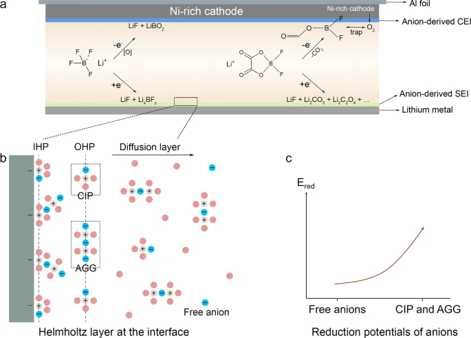
Herein, inspired by research studies, we proposed a novel strategy to solve the cointercalation of Li+-TMP into graphite by constructing a stable SEI film during the precycle process. That is, a stable SEI film is formed by precycling the Li||graphite half-cell with 1.5 M lithium difluoro(oxalato)borate (LiDFOB)-EC/DMC electrolyte. The preferred salt of LiDFOB makes Li+ easier to be desolvated because the solvation sheath structure containing DFOB– anions weakens the coordination ability between Li+ and solvent, resulting in a dense and stable SEI film mainly derived from DFOB–. (18) This can alleviate the direct contact between the TMP-containing electrolyte and graphite anode. In addition, the selected lithium concentration of 1.5 M achieves both low cost and good effect. Therefore, the as-generated dense and stable SEI film on the surface of graphite is relatively rich in LiF and lithium oxalate, which helps to restrain the cointercalation of Li+-TMP and improves the compatibility between TMP and graphite anodes. As a result, the modified Li||graphite cell shows a good flame-retardant property and excellent electrochemical performance, even if the 0.7 M LiDFOB-EC/DMC/TMP(40%) electrolyte is used in the subsequent cycles.
Experimental Section
Preparation of Electrolytes and Electrode
All electrolytes, including 0.7 M LiDFOB-EC/DMC (1:1 volume ratio) + xTMP (x = 20, 30, and 40%), 1.0 M LiDFOB-EC/DMC, and 1.5 M LiDFOB-EC/DMC (1:1, volume ratio), were prepared in an Ar-filled glovebox with water and oxygen contents less than 0.1 ppm. LiDFOB, EC, DMC (Guangdong Canrd New Energy Technology Co., Ltd., Co., Ltd.), and TMP (Zhang Jia Gang Ya Rui, Co., Ltd.) are battery-grade purities. The electrode was prepared by coating the slurry, which was composed of 92 wt% graphite active material and 8 wt% polyvinylidene fluoride onto a copper foil followed by vacuum drying at 110 °C for 12 h.
Electrochemical Measurements
The graphite anode with the preconstructed stable SEI film was marked as graphite@SEI. The abbreviations of cells corresponding to different electrodes and electrolytes are given in Table 1. The electrochemical charge–discharge cycling performance of half-cells was tested between 2 and 0.01 V on LAND testing systems. Electrochemical impedance spectroscopy (EIS) and cyclic voltammetry (CV) of the cells with different electrolytes were performed on CHI660E (Shanghai Chenhua, China) electrochemical workstations. The amplitude of EIS is 5 mV, and the frequency is 105–0.1 Hz. The scan rate of CV is 0.001 mV s–1, and the voltage range is from open-circuit potential to 0.01 V.
Table 1. Abbreviations of Cells Corresponding to Different Cells
| abbreviation of cell | electrolyte | anode |
|---|---|---|
| Li|0.7 M with 40%TMP|graphite | 0.7 M LiDFOB-EC/DMC/TMP(40%) | graphite |
| Li|1.5 M without TMP|graphite | 1.5 M LiDFOB-EC/DMC | graphite |
| Li|0.7 M with 40%TMP|graphite@SEI | 0.7 M LiDFOB-EC/DMC/TMP(40%) | graphite@SEI |
Electrolyte Properties and Electrode Characterization
The pure solvent DMC, TMP, EC/DMC/TMP, and 0.7 M LiDFOB-EC/DMC/TMP were measured by Raman. The electrodes after multiple cycles were disassembled from cells and rinsed with DMC for 3 times. After drying, the surface and cross-sectional state of the electrode was characterized by scanning electron microscopy (SEM), energy-dispersive X-ray spectroscopy (EDS), X-ray photoelectron spectroscopy (XPS), and atomic force microscopy (AFM).
Results and Discussion
The Raman spectrum was used to measure different electrolyte systems to clarify the coordination structure between Li+ and solvents, and lithium salt anions. As shown in Figure 1, Raman spectrum of 0.7 M based electrolytes with 20, 30, and 40% TMP, and 1.5 M LiDFOB-EC/DMC with and without TMP. Figure 1a shows the total Raman spectrum of the electrolyte system. Figure 1b shows the stretching vibration of B–O (LiDFOB) and P–O–C (TMP) bond in different electrolyte systems (722 and 738 cm–1). Figure 1c shows the stretching vibration of O–CH3 in DMC at 920 cm–1. Figure 1d shows the stretching vibrations of P═O, C–H and C═O at 1270, 1463, and 1764 cm–1, respectively. Herein, we will solve the problem of Li+-TMP cointercalation. Thus, we focused on the analysis of changes in P═O in TMP (Figure 1d). With the increase of TMP content, the P═O group moved toward higher wave number after Li+ was coordinated with TMP, and the wavelength decreased, resulting in a blue shift phenomenon, indicating that Li+ was coordinated with more TMP. (19) As we all know, the donor number (DN) value of TMP is 23, which is higher than that of EC (16.4) and DMC (15.1), respectively. As a result, Li+ will preferentially coordinate with TMP, and EC solvent with excellent film-forming performance will be excluded from the solvation sheath of Li+; DFOB– is also excluded from the solvation sheath and becomes a free anion. This solvation structure is unstable, resulting in poor reduction stability of the electrolyte. (20)

In addition, the main characteristic peak of LiDFOB is 1764.95 cm–1, which is the out-of-plane swinging vibration of C═O. In Figure 1d, the C═O bond in DMC is 1753 cm–1. The stretching vibration of the C═O bond in LiDFOB is 1764.95 cm–1. In the 1.5 M LiDFOB-EC/DMC electrolyte, the stretching vibration of the C═O bond is particularly obvious, the wave number of Li+–C═O increases (1800 cm–1), the wavelength decreases, and the peak intensity also increases significantly. It indicates that more DFOB– enters the solvation shell. In the 0.7 M LiDFOB-EC/DMC/TMP (20, 30, and 40%) electrolyte, the Li+–C═O wave number increases to 1794 cm–1. In conclusion, the increase of electrolyte concentration has a great influence on the coordination structure of Li+ and lithium salt anions. Therefore, a stable SEI film can be formed after the reduction of the 1.5 M LiDFOB-EC/DMC electrolyte, which lays a foundation for the subsequent prefilm formation process.
To study the influence of the cointercalation of Li+-TMP on LIBs, the discharge test was carried out on batteries with different TMP contents (20, 30, and 40%, respectively). As shown in Figure 2a–c, the discharging voltage plateau at about 1.7 V is attributable to the prior decomposition of LiDFOB salt, which is expected to form an initial and effective SEI film to restrain the cointercalation of Li+-TMP into graphite. However, the subsequent voltage decline corresponding to the decompositions of TMP (below 0.9 V) is extended with the increase of TMP content from 20 to 40%, indicating that the cointercalation of Li+-TMP into graphite is getting worse and worse, accompanied by the increase of electrolyte decomposition and the aggravation of graphite layer stripping. (21) With the increase of TMP content, Li+ will be surrounded by TMP molecules instead of the carbonate solvent to a greater degree. When Li+ coordinates with strongly polar TMP, Li+ absorbs electrons from the P═O group with unpaired electrons in TMP, resulting in a decrease in the electron cloud density of TMP. As a result, Li+-TMP is more likely to gain electrons on the negative side of the electrode and undergoes violent decomposition of the electrolyte. (22) That is, the initial SEI film formed by the reduction of the 0.7 M LiDFOB-EC/DMC electrolyte cannot effectively improve the compatibility between TMP and graphite anodes.

In addition, the combustion state of the electrolytes with 20, 30, and 40% TMP in EC/DMC solvent was observed. As shown in Figure 2d–f, the flame retardancy of the electrolyte is increased with the content of TMP increasing from 20 to 40%. In particular, the carbonate solvents can be completely unburned when the amount of TMP reaches 40%. (23) Therefore, the full compatibility between the electrolyte containing 40% TMP and graphite anode is of great significance to completely solve the safety performance of LIBs.
To improve the compatibility between the electrolyte containing 40% TMP and graphite anode, the strategy of preconstructing a stable SEI film has been designed. That is, the stable SEI film was preconstructed by cycling the battery in LiDFOB-EC/DMC electrolyte five times (denoted as graphite@SEI). Then, the cell was reassembled by replacing LiDFOB-EC/DMC with the 0.7 M LiDFOB-EC/DMC/TMP(40%) electrolyte.
Figure 3a–c give the charge–discharge curves of reassembled cells which have been precycled in LiDFOB-EC/DMC electrolytes with different salt concentrations of 0.7, 1.0, and 1.5 M, respectively. It is of interest that the reassembled Li||graphite@SEI cell with the 0.7 M LiDFOB-EC/DMC/TMP(40%) electrolyte can maintain a high reversible capacity (Figure 3c) after precycling in 1.5 M LiDFOB-EC/DMC. In particular, for the reassembled Li|0.7 M with 40%TMP|graphite@SEI cell which is precycled with the 1.5 M LiDFOB-EC/DMC electrolyte, the coulombic efficiency has been maintained near 100% from the 1st to the 50th cycles, and the capacity is still as high as 353 mAh g–1 even after 50 cycles. By comparison, both the coulombic efficiency and the capacity have consistently been kept at a low level during the first 25 cycles for the Li|0.7 M with 40%TMP|graphite cell. After 25 cycles, the cell capacity remained stable because the first cycle of the Li|0.7 M with 40% TMP|graphite cell, Li+-TMP cointercalated into graphite, resulting in the continuous decomposition of TMP. The H3PO4 was generated by TMP reduction, which dissolves in the electrolyte and cannot form a stable SEI film. Therefore, the diffusion behavior of Li+ is irreversible, resulting in a low specific capacity. In the subsequent cycles, the SEI film continues to grow. In the 25th cycle, the SEI film gradually tended to be stable, because LiDFOB and EC started to form a more stable SEI film when TMP was consumed essentially. It is generally accepted that the stable SEI is essential for the excellent electrochemical performance. This indicates that the SEI film preconstructed by 1.5 M LiDFOB-EC/DMC can effectively inhibit the cointercalation of Li+-TMP into graphite.

The electrochemical behaviors of the Li|0.7 M with 40%TMP|graphite, Li|0.7 M with 40%TMP|graphite@SEI, and Li|1.5 M without TMP|graphite cells were studied by the CV test. As shown in Figure 4a, a large reduction current occurred in the Li|0.7 M with 40%TMP |graphite cell during the initial cycle, indicating a serious decomposition of the 0.7 M LiDFOB-EC/DMC/TMP(40%) electrolyte. (24,25) Worse than that, the reaction on the electrode surface is irreversible, leading to the cycling capacity degradation and safety issues. (26) Interestingly, the reversibility of the reassembled Li|0.7 M with 40%TMP|graphite@SEI cell (Figure 4b) is significantly enhanced, being on a par with nonflame-retardant Li|1.5 M without the TMP|graphite cell (Figure 4c). This indicates that the cointercalation of Li+-TMP into the graphite anode is inhibited in the reassembled Li|0.7 M with 40%TMP|graphite@SEI cell, and the compatibility between TMP and graphite has been improved. (27)

The EIS test was performed on the cells after the initial film formation. (28) As shown in Figure 4d–f and Table 2, we can see that the Li|0.7 M with 40%TMP|graphite cell has high impedance. The reason for this is mostly that Li+ is coordinated with TMP with strong polarity, making the Li+ difficult to be desolvated. Because of the failure of the desolvation process, a large number of Li+-TMP will be cointercalated into the graphite anode and reductive decomposition to produce a thick organic polymer SEI film, resulting in slow migration of Li+ and uneven charge distribution. After preconstructing a stable SEI film, Rf of the reassembled Li|0.7 M with 40%TMP|graphite@SEI cell is significantly reduced from 143.3 to 62.54 Ω, which is closer to that of the nonflame-retardant Li|1.5 M without TMP|graphite cell. Thus, it can be seen that the graphite@SEI can not only effectively inhibit cointercalation of Li+-TMP, but also improve the rate performance of the cell.
Table 2. Fitting Results of EIS Data of Li|0.7 M with 40%TMP |Graphite, Li|0.7 M with 40%TMP|Graphite@SEI, and Li|1.5 M without TMP|Graphite Cells after the Initial Discharge Process
| cells | Rf (Ω) | Rct (Ω) |
|---|---|---|
| Li|0.7 M with 40%TMP|graphite | 143.3 | 46.64 |
| Li|0.7 M with 40%TMP|graphite@SEI | 62.54 | 51.48 |
| Li|1.5 M without TMP|graphite | 16.99 | 2.92 |
The top-view and cross-sectional SEM images were used to further illustrate the effect of graphite@SEI. For the graphite electrode in the Li|0.7 M with 40%TMP|graphite cell, it is found that the SEI film is thick after five cycles because of the decomposition of TMP and the formation of polyphosphate (marked with the circle red-dotted box in Figure 5a,b). (29) In addition, the graphite has separated from the copper foil current collector in cross-sectional characterization, caused by the cointercalation of Li+-TMP into graphite. We find, quite interestingly, the graphite surface is dense in Li|1.5 M without TMP|graphite (Figure 5c,d), which helps to effectively inhibit the negative side reactions. (30) This indicates that the SEI film derived from DFOB– is a feasible strategy to improve the interfacial stability. The SEM image of the reassembled Li|0.7 M with 40%TMP|graphite@SEI cell in Figure 5e,f, as expected, shows a similar SEI film with the one in the Li|1.5 M without TMP|graphite cell, which is much thinner and denser than that in the Li|0.7 M with 40%TMP|graphite cell. That is, the preconstructed SEI film derived from the cycling of the Li|1.5 M without TMP|graphite cell contributes to the improvement of interfacial stability.

From what has been discussed above, we may safely draw the conclusion that the thickness and roughness of the SEI film are crucially important for suppressing cointercalation. The thickness of the preformed SEI on graphite was also studied (Figure S1). To further prove the SEM characterization results, the electrode morphology of the different SEI films was characterized by AFM, and the detailed values of roughness are given in Table 3. Herein, the ″tapping mode″ is used, because it has less contact with the sample surface during the scanning process, which causes less damage to the sample. (31) Pink and green represent the high and low point. (32) As shown in 2D and 3D AFM images of Figure 6a–c, the SEI film of Li|0.7 M with 40%TMP|graphite is uneven (the roughness is 323 nm) and thick, which is consistent with Figure 5a,b. By contrast, as shown in Figure 6d–f, the roughness of the SEI film formed in the reassembled Li|0.7 M with 40%TMP|graphite@SEI cell is obviously decreased due to the preconstructed thin and even SEI film, converging toward nonflame-retardant Li|1.5 M without TMP|graphite cell (Figure 6g–i).

Table 3. Surface Roughness of Different Cells
| cells | root-mean-square roughness (Rq)/nm | mean roughness (Ra)/nm |
|---|---|---|
| Li|0.7 M with 40%TMP|graphite | 323 | 268 |
| Li|0.7 M with 40%TMP|graphite@SEI | 201 | 160 |
| Li|1.5 M without TMP|graphite | 67.9 | 55.9 |
EDS was used to clarify the components of SEI film formed by the reduction of electrolytes on the graphite surface. (33) Compared with the Li|0.7 M with 40%TMP|graphite cell (Figure 7a), the content of the P element is significantly decreased in the reassembled Li|0.7 M with 40%TMP|graphite@SEI cell (Figure 7b), resulting from the inhibited Li+-TMP co-intercalation and the reduced TMP decomposition. In addition, the distribution of C, F, B, and P elements is more uniform on the surface of graphite@SEI electrode (Figure 7), which suggests that the preconstructed SEI film helps to suppress the side reactions between electrolyte components and graphite.

The composition of the SEI film was analyzed by XPS, and the results are given in Figure 8. In the C 1s spectra, C═O (289 eV) and C–O (287 eV) peaks are mainly from oxalic acid generated by LiDFOB decomposition. (34) It can be seen that the intensity of C═O and C–O peaks in each of the SEI films formed in Li|1.5 M without TMP|graphite and Li|0.7 M with 40%TMP|graphite@SEI cells is significantly higher than that formed in Li|0.7 M with 40%TMP|graphite. This indicates that more LiDFOB salts are self-decomposed in both the Li|1.5 M without TMP|graphite and Li|0.7 M with 40%TMP|graphite@SEI cells, because of the continuous employment or precycling with the 1.5 M LiDFOB-based electrolyte. That is, more DFOB– anions are included into the solvation sheath in the 1.5 M LiDFOB-EC/DMC electrolyte, which makes Li+ easier to be desolvated and weakens the coordination ability between Li+ and solvent. It contributes to the formation of a dense and stable SEI film, alleviating the direct contact between the TMP-containing electrolyte and graphite anode, and thus improving the electrochemical and safety performances of LIBs.

Accordingly, the peak intensities of Li–F (685 eV) and B–F (687 eV) in the F 1s spectra and the peak intensities of B–F (195 eV) and B–O (192 eV) in the B 1s spectra for Li|1.5 M without TMP|graphite and Li|0.7 M with 40%TMP|graphite@SEI cells are correspondingly higher than those for the Li|0.7 M with 40%TMP|graphite cell. (35−37) In addition, according to the binding energy of P 2p (133 eV), it is found that the content of P in the SEI film in the Li|0.7 M with 40%TMP|graphite@SE cell is much lower than that in the Li|0.7 M with 40%TMP|graphiteI cell, indicating that the decomposition of TMP is significantly suppressed by the prior decomposition of LiDFOB. (38) Therefore, we believe that the compositions of the SEI film formed in the reassembled Li|0.7 M 40%TMP|graphite@SEI cell are dominated by inorganic lithium oxalate, LiF, and boron-containing polymers, which helps to restrain the cointercalation of Li+-TMP and improves the compatibility between TMP and the graphite anode. (39,40)
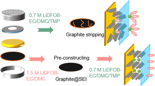
Figure 9 gives the schematic of making overall planning for flame-retardant property and cycle performance improvement. A stable SEI film on the graphite surface is preconstructed by cycling the Li||graphite half-cell with the 1.5 M LiDFOB-EC/DMC electrolyte for five cycles. In this case, more DFOB– anions are included into the solvation sheath, which makes Li+ easier to be desolvated, weakens the coordination ability between Li+ and solvent, and contributes to the formation of a dense and stable SEI film. The as-generated stable SEI film is relatively rich in LiF and lithium oxalate, which restrains the direct contact between the TMP-containing electrolyte and graphite anode, and thus improves the compatibility between TMP and the graphite anode. As a result, the modified Li||graphite cell enables a good flame-retardant property and excellent electrochemical performance, even if the 0.7 M LiDFOB-EC/DMC/TMP(40%) electrolyte is used in the subsequent cycles.

Conclusions
In this work, we improved the compatibility between flame-retardant TMP solvent and graphite anode by preconstructing a stable SEI film on the surface of graphite, which improves the safety performance of LIBs without sacrificing the capacity. In particular, the prior decomposition of LiDFOB salts and the preformation of SEI films rich in LiF, lithium oxalate, and boron-containing polymers dominate the good flame-retardant property and excellent electrochemical performance. Extending studies like this will be required to look for more suitable film-forming additives.
【Article link】
https://doi.org/10.1021/acsaem.2c01862