Arjun S. Kulathuvayal and Yanqing Su*
Cite this: ACS Appl. Energy Mater. 2023, 6, 11, 5628–5645
Publication Date:May 22, 2023
Abstract
This review aims to give a collective analysis of ionic transport mechanisms through the solid electrolyte interphase (SEI) in lithium-ion batteries. In electrochemical cells, the SEI is the least understood and most important complex thin layer that forms on electrodes when they come in contact with electrolytes. Though the SEI is the key factor in any electrochemical cell, the complete picture of the SEI is still fuzzy because of its diverse and dynamic nature. To address the complexity of this interphase, the fabric of this review is arranged in such a way that each component of the SEI is separately analyzed by means of its chemical structure and the possible diffusion mechanism. Since most of the studies about ionic transport through the SEI are based on first-principles studies, a section of this review is devoted to discussing the theoretical concepts of ionic transport. Further, this review has audited other possible means of ionic transport occurring through grain boundaries including open channels. A brief overview of the electronic conductivity of SEI components is also included herewith.
1. Introduction
Lithium-ion batteries (LIB), one type of metal-ion batteries, are the gateway to reliable and sustainable energy storage. A report of the International Energy Agency says that after COVID-19 restrictions were lifted worldwide, rebounding transport activities led to an 8% jump in CO2 emissions in 2021 over the previous year. (1) Given the emerging scenario of electric vehicles (EVs), where lithium-ion batteries are one of the integral parts, these greenhouse emissions can be reduced by a great extent. Global sales of electric passenger vehicles are projected to surpass 10.5 million in 2022, which is about 4 million above the year-2021 level, the research firm Bloomberg NEF said in a recent report. (2) Despite being a promising candidate, LIBs still need to be improved for far-reaching high energy density applications for high-mileage electric vehicle applications. (3,4) The energy density of the commercialized LIBs used in EVs ranges from 140 to 250 W·h kg–1. (5,6) Apart from the energy density, other properties of LIBs need to be improved, including reliability, cost effectiveness, and charging speed; in addition, factors affecting the thermal runaways have to be optimized further.
The structure of a LIB is similar to any other electrochemical cell in that it has a solid anode and cathode and an electrolyte which could be in either a solid or a liquid phase. (7,8) An illustration of the major components of a typical LIB with their relative thickness has been depicted in Figure 1. The solid electrolyte interphase (SEI) layer (sometimes referred to as an interface) is a thin multilayer complex structure with several hundreds of Angströms thickness formed between the electrode and the electrolyte. This layer is formed from the electrochemical redox reactions of the electrolyte and electrode during the first few charging and discharging phases. Later, this interphase is subjected to subtle chemical and physical changes due to ionic transport resulting from the electrochemical cycling of the battery. Generally, the SEI serves as a gateway for the ionic transport between the electrode and the electrolyte. (7,9) Because of this reason, the SEI is one of the key factors that control the Li-ion distribution to the matrix of the electrode. A uniform Li-ion distribution is required for the optimum intercalation; otherwise, the aggregation of Li ions around the protrusions on the surface electrode gives rise to the growth of lithium dendrite, consequently leading to short circuiting inside the battery. (10) Generally, a SEI forms on the surface of the anode as well as the cathode.

This review particularly focuses on the SEI formed on a carbon-based anode material because of its adequate Li-ion intercalation (LiC6) and widespread commercialization. It was found that the SEI formed on graphite is more stable when compared to other electrodes such as lithium composite based, graphite based, and silicon based. (11,12) Meanwhile, silicon–graphite composite offers higher Li-ion intercalation (Li3.75Si) than pure graphite-based electrodes, but it suffers from huge volume expansion in the Li22Si5 phase (about 300%), resulting in mechanical instability of the host material owing to the mechanical stress developing inside. (13−15) The volume expansion and the associated cracking on such electrodes can be solved to an extent by controlling the morphology of the SEI. (16) Also, it is well known that in lithium–silicon composite, the theoretical specific capacity of the battery ranges from 3500 to 4200 mAh g–1 because of its higher intercalation ratio, and this is nearly 11 times that of graphite-based electrodes (372 mAh g–1). (17)
The concept of a SEI was introduced by Peled (18) in 1979 and later improved by Aurbach et al. (19) in 1999. The major components of a SEI are the precipitates of inorganic salts, and together with the organic components, this interphase plays an imperative role in the cycling stability of the anode. (20) Moreover, the SEI has a significant role in ionic transport through LIBs as this layer is permeable to Li ions and prevents the tunneling of electrons and electrolyte molecules between the electrode and the electrolyte, thereby providing electrochemical stability to the cell. (21) Nevertheless, this passive layer consumes nearly 2–5% of active Li ions for its irreversible formation and a few more percentages in the subsequent cycles while resulting in the gradual fading of the capacity, Coulombic efficiency, and overall performance of the battery. (22) Further, the cracking of the SEI accelerates the lithium dendrite formation, which leads to short circuiting and hence the thermal runaways of the battery pack. In short, the SEI is a necessary layer for LIBs, even for the broader concept of metal-ion batteries, but it has certain constraints as mentioned.
The major components of the SEI layer associated with graphite-based anodes are lithium fluoride (LiF), lithium oxide (Li2O), lithium carbonate (Li2CO3), lithium hydroxide (LiOH), lithium oxalate (Li2C2O4), lithium nitride (LiN), dilithium ethylene glycol dicarbonate (CH2OCO2Li)2Li2EDC, lithium methyl carbonate (LiOCO2CH3), dilithium butylene dicarbonate (Li2BDC), and lithium ethyl carbonate (LiOCO2C2H5) at temperatures in the range of 250–400 K. (23) The SEI is generally modeled as a complex multilayered mosaic-type structure with an inorganic inner layer close to the electrode and an organic porous heterogeneous outer layer close to the electrolyte. (24) There are models such as “two-layer-two-mechanism diffusion” developed by Shi et al., (25) and studies by Lu et al. (26) corroborate the multilayer structure of the SEI. (27) Since the organic layer of the SEI has a porous structure, Li-ion transport through this part can be understood through Fick’s laws of diffusion and must be optimized to obtain a higher ionic transport rate. (25,28) Ionic transport through the inorganic layer of the SEI varies from component to component and is mainly carried out through vacancy diffusion, concerted exchange, knock-off, and direct hopping mechanisms. (29) Also, substantial Li-ion transport is also happening through grain boundaries of the aforementioned inorganic components. Meanwhile, analysis of ionic transport through electrolytes and separators shall be accounted for in the encyclopedic understanding of ionic dynamics in LIBs. There are many review articles available on the ionic transport through separators including various solid and liquid electrolytes in LIBs. (30−36)
Since a SEI is chemically active and dynamic during the charging and discharging phases, it is quite difficult to understand the driving mechanisms of Li-ion transport through in situ experimental studies. In this scenario, the ab initio tools, mainly density functional theory (DFT)-based computing schemes, are more fruitful. (37−39) Other computational schemes such as phase field modeling and molecular dynamics have also been utilized to model the formation, growth, cracking, and dissolution of the SEI. (40−42) Given the available literature reviews about the SEI formation, growth, dendrite growth, properties, functionalities, failure modes, and artificial SEI design, this review is predominantly focused on the various ionic transport models across the SEI associated with carbonaceous anodes. (11,43,44)
There are many research articles and reviews on the chemical structure, stability, formation mechanism, and properties of the SEI. (11,23,24,44−47) However, a collective auditing of Li-ion transport and the associated diffusion mechanisms through the SEI is not yet documented. The reason is that the diverse chemical nature of the SEI stems from the nature of electrolytes, electrodes, and the formation atmosphere. To address this complexity, we organize the fabric of this review in such a way that each component of the SEI layers (mainly the inorganic layer) is separately accounted for in the analysis by means of its chemical structure and possible diffusion mechanism. Apart from the individual components of the SEI, we paid attention to other possible means of ionic transport happening through the grain boundaries (GBs) and open channels in the SEI. A brief overview of the electronic conductivity of the SEI components is also included herewith. Further, we review all available ionic transport models developed to date for a fruitful comparison study. A theoretical overview of diffusion studies and related theoretical concepts are also documented.
2. Structure of the SEI Layer in LIBs
Formation of the SEI is due to the redox reaction between the electrolyte and the electrode in all LIBs. The structure and composition of this film are highly influenced by the surface morphology of the electrode and the chemical composition of the electrolyte. (48) Electrochemistry of the formation reaction states that when the energy of the lowest unoccupied molecular orbital of an electrolyte molecule stays lower than the highest occupied molecular orbital of an electrode’s molecule, the electrons reduce the electrolyte and form a complex bilayer on the surface of the electrode. Beginning from the primitive work of Peled, (18) a lot of advances have contributed to obtaining the modern picture of the SEI. Up to this date, a promising model explaining the structure of the SEI is a “the multicomponent, multilayer structure”. (49−52) According to this model, the SEI is a two-layer thin film composed of an organic outer layer close to the electrolyte and an inorganic inner layer close to the electrode. Figure 2 provides a detailed illustration of the SEI as described in the aforementioned model. During the first charging phase, lithium ions from the cathode drift through the electrolyte and get reduced by the anode along with a fraction of electrolyte molecules, thus forming a complex bilayer on the anode. A very similar redox reaction also takes place on the cathode surface and forms an SEI on its surface. The SEI formed on a lithium-based cathode has been subjected to vigorous research activities in the past decade because it has a direct influence on dendrite growth and prevention measures. (10,53,54)

The nature of the chemical components present in the inorganic layer of the SEI depends upon the electrolyte (along with the additives and stabilizers) and the electrode material. A summary of the recently emerged LIB configurations and the associated SEI components is listed in Table 1. The structural properties of the SEI depend upon the surface chemistry, temperature, voltage range during cycling, and cycling protocol, wherein the time spent at low potentials is a crucial factor. (55) Generally, the inorganic layer is composed of grains of LiF, Li2O, LiOH, and Li2CO3, and the lithium-ion transport through this layer takes place through grains and GBs of aforesaid components. (56) After the charging phase, a negligible fraction of electrons from the anode tunnels through the formed inorganic layer, reduces a fraction of the electrolyte molecules, and hence forms a thicker porous outer organic layer. The components of this layer are mostly organic complex molecules based on the chemical composition of the electrolyte and additives. (50)
Table 1. Recent Advances in SEI Components with Their Associated Anode, Cathode, and Electrolytes (2019 onward)
| cathode | electrolyte | anode | SEI components | comments |
|---|---|---|---|---|
| Li foil (thickness 0.25 mm) | 1 M LiTFSI in 1,1,2,2-tetraethoxyethane with microporous polypropylene (Celgard 2325) and glass fiber as separators. | silicon–graphite compositea | Li2SO, Li3N, hydrocarbons, functional groups such as H3C–O– or – H2C–O–, –CO2, –CF3, –O–C–O–, etc. (69) | SEI accommodates the volume changes in the Si/graphite electrode and hence gives a good electrochemical performance; also, the formed SEI is smooth and continuous |
| Li-based cathode | 1.2 M LiPF6 in EC:EMC (3:7 w/w) | pseudographite | poly(ethylene oxide) (PEO)-type polymers, alkyl carbonate (R–CH2OCO2– , R–CH2OCO2−) LiF, lithium alkoxide (R–O–Li), LixPOyFz (70) | a specially synthesized graphite electrode (from the “University of Idaho thermolyzed asphalt reaction”) with defects |
| NMC622/CNT/super P/PVdFb | 1 M LiPF6 electrolyte in ethylene carbonate:diethylene carbonate:ethyl methyl carbonate; in a ratio of 3:3:4 with SC1622 as the separator | graphite/super P/PVdFc | LiF, LiPF6, Li2CO3, Li2O, LixPOyFz, carbonate groups, oxy fluorophosphate group (71) | Li2CO3, Li2O, and LixPOyFz are the inner inorganic SEI components, and carbonate groups, Li2O, and the oxy-fluorophosphate groups are the outer inorganic components stemming from the electrolyte decomposition |
| pure lithium | 1 M LiPF6 dissolved in an ethylene carbonate (EC) and diethyl carbonate (DEC) mixture(1:1 volume percentage) | graphite | LiF, Li2CO3, components on a graphite surface showing covalent CF bonds and semi-ionic CF bonds (72) | Celgard 2400 has been used as the separator; also, here fluorine atoms have been introduced on the graphite surface using CF4 gas |
| lithium foil | 1 M LiPF6 in ethylene carbonate (EC: dimethyl carbonate (DMC) (1:1, vol) with a glass microfiber filter as the separator and fluorosulfonyl isocyanate as the electrolyte additive | graphite | LiF, LiPxOyFz, Li2CO3, Li2O, Li2SO4, ROSO2Li, Li2S, Li2SO3 (73) | LiF originates from either LiPF6 or FI decomposition; inorganic layer is mainly composed of LiF, Li2SO4, ROSO2Li, Li2S, Li2SO3, and a low concentration of Li2CO3, Li2O, and LixPFyOz; outer layer is made of organic polymeric species |
| pure lithium | adiponitrile/dimethyl carbonate-based (DMC) electrolytes along with lithium bis(oxalate)borate or lithium bis(fluorosulfonly)imide and Freudenberg FS2026 nonwoven polypropylene used as the separator | graphite | LiF, ROLi, Li2CO3, organic carbonates, lithium carbide,b groups such as SO3–2 and polysulfur (or polysulfide), and decomposition products of lithium difluoro(oxalato)borate (LiDFOB) with B–O bond (74) | ROLi forms as a reduction product of DMC and deposits close to the graphite surface; LiDFOB reduction leads to a more protective SEI layer; The combination of LiDFOB with FEC leads to a low-resistance SEI with a high LiF content |
| NMC111d | fluorine-free electrolyte based on lithium bis(oxalato)borate and vinylene carbonate (VC) | silicon–graphite composite | polymeric species formed by VC, reduction products of the bis(oxalato)borate anion (75) | forms a stable oxygen-rich SEI; capacity fading occurs during long-term cycles due to the higher impedance across the SEI while showing good cycling stability at higher temperatures |
| NMA90e | 20 wt % of FEC and 1 wt % of lithium 4,5-dicyano-2-(trifluoromethyl)imidazole (LiTDI) in 1.5 M LiPF6 in EMC electrolyte | graphite | inorganic layer rich with LiPF6 and carbonate solvents decomposition products and organic layer composed of LiTDI-derived species, N-containing species (76) | forms a good passivation layer since the SEI evolved from fluoroethylene carbonate; also, LiTDI decomposes and modifies the SEI layer, leading to mitigated electrolyte decomposition |
a
Binder: lithium polyacrylate and LiF, Li2S, Li2S2O4, and Li2SO3.
b
In a ratio of 94.0/0.75/3.0/2.25 and cast onto Al foil. The loading level is 15.84 mg/cm2, and the thickness is 68 μm.
c
In a ratio of 91.0/1.0/8.0 and deposited on Cu foil with a loading level of 8.55 mg/cm2 and a thickness of 69 μm.
d
LiNi1/3Mn1/3Co1/3O2.
e
LiNi0.9Mn0.05Al0.05O2.
The fabric of the inorganic layer associated with carbonaceous electrodes was put forward by Peled, Golodnitsky, Menachem, and Bar-Tow. (57) They suggested that LiF, Li2CO3, LiCO2-R (R represents the organic species linked to the carbon atom), Li2O, lithium alkoxides, and nonconductive polymers are the major components of this layer. Later, this fact was corroborated through surface analysis that the inorganic layer is mainly formed by LiF, LixPFy, PFy, Li2CO3, and Li2O, based on the cycling stage and the electrolyte’s chemical composition. (58−61) The phase of this inorganic layer was revealed in a cryogenic electron microscopic study conducted by Zheng et al., (62) showing that the nanocrystalline inorganic components, namely, LiOH, Li2O, Li2CO3, and LiF, are embedded as the amorphous organic phase. Shi et al. (25) have corroborated the concept of conductivity across this layer and have postulated that the electronic conduction is primarily obstructed by the inorganic constituents. However, they also suggest that rapid Li-ion conduction is facilitated by Li2CO3 and Li2O components.
In the SEI, the organic and inorganic layers together serve as a dielectric membrane, and its dielectric characteristics significantly influence uniform lithium deposition on the electrode by maintaining a uniform current/potential distribution throughout the layer and suppressing lithium protrusions. (63,64) Various types of dielectric breakdowns are reported in LIBs (electrolytes, separators, and electrode materials have dielectric characteristics). These breakdowns usually end up in thermal runaways. The thermal runaways originating from the SEI are particularly associated with the metastable components present in the organic layer of the SEI. (65,66) Therefore, proper attention to this layer shall be given during the designing of a battery pack. In addition to this, promising SEIs must have high elasticity, strong lithium-ion affinity, and hydrophilic properties, which make them withstand the dielectric breakdown and prevents dendrite formation. (67) Furthermore, the consumption of active Li ions (2–18%) during the formation of the SEI and successive cycles shall be optimized for the efficient cycling performance of the battery. (68)
2.1. Factors Affecting the Structure of the SEI
2.1.1. Binders
Binders ensure the cohesion of the active material (electrode) particles to the current collector plate while being electrochemically stable. Popular binders used in Li-ion batteries are poly(vinylidene fluoride) (PVdF) and carboxymethylcellulose sodium salt (CMC), wherein CMC is found to be an excellent binder for carbonaceous as well as noncarbonaceous silicon-based electrodes. (77) In addition to this, CMC has a beneficial role in the irreversible capacity of a graphite electrode and helps form a stable SEI with a low carbon content. (78) PVdF is also a good binder but cannot endure the substantial volume changes on lithiation and hence cannot be used in silicon–graphite-based electrodes. (79)
Binder material chemistry influences the formation of the SEI. Chai, Qu, and Zhang have reported that the presence of less reductive species in the SEI during the first cycle significantly improved the Coulombic efficiency of their newly proposed chitosan-based electrode when compared to the conventional PVdF-based anode. (80) The selection of a polymer binder, such as CMC or PVdF, has a noteworthy impact on the irreversible deformation of the electrode, which implies that the formation and growth of the SEI layer is influenced by the polymer binder. (81) Similarly, Nafion─a binder additive─has been reported to optimize the morphology and structural stability of the SEI. (82) These studies point toward the fact that the SEI’s structure can be influenced by the chemical composition of the binder and its physical properties. In short, the development of an efficient binder material that is compatible with the SEI is inevitable for developing a stable and efficient battery pack.
2.1.2. Separator
The separator is the packing component in LIBs that serves as the boundary between the electrode and the electrolyte and stays very close to the SEI. The position of the separator and its relative thickness is shown in Figure 1. The separator provides structural integrity to the battery pack in such a way that it serves as a rigid, selectively permeable wall between the cathode, the electrolyte, and the anode. A good separator should have properties including good porosity, temperature tolerance, mechanical strength, and chemical inertness toward the battery components. Moreover, this thin layer (thickness ≈ 20–30 μm) facilitates the ionic shuttling through its micropores between electrodes. (83,84) The role of a separator in a battery is to prevent the internal short circuit arising from various reasons, such as dendrite growth, leakage of liquid electrolytes, and extrusion of metal electrodes. (85) For safety reasons, most separators are multilayered, designed with a circuit-breaking feature, where certain layers have different phase transition temperatures. As the temperature of a cell increases, the lower melting component melts and seals the pores of the adjacent separator layer and stops the ionic transport and hence the current flow in the battery pack. (85) Generally, there are three classes of separators based on their synthesis mode and porosity: (1) composite separators, which synthesized by coating organic/inorganic materials on the surface of commercial polyolefin, (2) nonwoven separators, which are prepared by reinstating organic or inorganic materials inside or on the fiber surface of commercial polyolefin, and (3) the porous separators prepared by the solution-casting method. (86) Work on ultrathin multilayers of commercial PE separators made with poly(acrylic acid) and ZrO2 found that the surface chemistry of the separator influences the formation of the SEI and provides additional stability to the layer. (87)
Ionic transport through the separator occurs through a convection-driven mechanism if the pore size is on the order of nanometers, and it becomes a diffusion-driven mechanism when the pore size reduces further. (88) In an in situ study on the hydraulic pressure of the electrolyte in a vanadium redox battery, Li et al. (89) examined the convection through a microporous separator and found that the convection is mediated by differential hydraulic pressures on both sides of the separator. Diffusion-mediated ionic movement depends on the size, configuration, and total volume of the pore spaces which hold the electrolyte. Apart from that, the chemical interaction effect, associated with polar groups or sites in the membrane substrate, also affects the diffusion by either elevating or depressing the diffusion coefficient selectively. (90) The area to improve in a separator is the development of a potential and chemically compatible separator that can sense and circumvent the thermal runaways and maintain a uniform ionic conductivity from the electrolyte to the electrode.
2.1.3. Additives
Additives are chemicals mixed with electrolytes at a particular proportion to prevent or enhance specific properties of electrolytes and the SEI layer. Fluoroethylene carbonate (FEC) and vinylene carbonate (VC) are widely used for commercialized additives. (91,92) These additives facilitate the formation of inorganic LiF and Li2CO3 components in the SEI. (93) There are diverse categories of additives with specific usages. One example is that the addition of flame-retardant additives (such as phosphorus- and halogen-based compounds) into traditional flammable electrolytes mitigates thermal runways to an extent. (94) However, such additives depress the ionic conductivity of the electrolyte and deteriorate the electrodes. (95,96) Jankowski et al. (97) reported that special functional additives are helpful for the controlled and rapid formation of the SEI, which circumvents the capacity decay of the battery. Similarly, Yang et al. (98) reported that an additive named octadecylamine (ODA) in a conventional electrolyte (1.2 M LiPF6 in EC/DMC) with vinyl carbonate (VC) additive enhances the ionic conductivity and physicochemical stability of the SEI in NCM-811∥Ti-SiOx@C full cells. Also, they posit that ODA additives can be easily decomposed on the surface of Ti–SiOx@C anodes compared to VC additives. In a DFT-based work on additives, Park et al. (99) stated that lithium tetrafluoro(fluoromalonato)phosphate (LFMP) as a dual-functional electrolyte induces a LiF-rich SEI on graphite anode NCM811/graphite cells at 60 °C. Also, they observed that the SEI formed has a weak binding affinity to PF5 and favors the formation of LiF. Recently, Xu et al. (100) put forward a gradient SEI model with surface-rich polycarbonate in which they combined the advantages of a flexible polymer and a high touristy ceramic through a liquid alloy electrolyte additive. Moreover, they have theoretically and experimentally verified that the gradient SEI created by the liquid alloy electrolyte additive accommodates the volume change and mitigates the dendrite suppression. Such additives are suitable for silicon-graphite-based electrodes, where volume expansion is challenging. (17)
2.1.4. Recent Advances in SEIs: Artificial SEI
Artificial SEI is a crucial and growing field related to LIBs, especially when designing a SEI with particular properties, such as the capacity to mitigate dendrite growth and volume expansion of electrodes and the ability to facilitate a fast and uniform ionic distribution to the electrode. (101) The need for the development of an artificial SEI is significant when the naturally formed SEI degrades during the cycling of the battery, as in potassium-based metal-ion batteries. (102) The primitive concepts of an artificial SEI were put forwarded by Kim et al. (103) in a work on the Kawasaki mesophase fine carbon electrode (KMFC). In that work, the authors coated a Li2CO3 layer on KMFC electrode using PVdF as a binder and found that the artificial SEI provides good ionic conductivity and suppresses the electrolyte decomposition. Later, Menkin et al. (104) proposed an artificial SEI that stabilizes the structure of graphite and a tin–copper anode on cycling, synthesized through electropainting and vacuum-insertion techniques. Recent work by Luo et al. (105) shows that Li3N, popular for its high mechanical strength along with cellulose, is a promising candidate for an artificial SEI on lithium electrodes. The cellulose was introduced using nitrocellulose as an electrolyte additive, and their results demonstrate a uniform lithium-ion distribution and suppression of dendrite growth on the lithium electrode. In another work, Chen et al. (106) constructed an artificial inorganic SEI layer composed of ZrO2, Li2O, Li3N, and LiNxOy rich with GBs on the surface of Li metal and found that the resulting LiZrO(NO3)2@Li electrode has a stable cycle life of about 550 h at a high current density of 10 mA cm–2 and mitigates dendrite growth.
Generally, an artificial SEI is fruitful for mitigating the volume expansion of electrodes in lithiation. For instance, a novel material derived from an elastic nanoparylene layer was found to be a promising artificial SEI layer capable of handling the large volumetric changes exhibited by Si-based electrodes. Specifically, parylene F and N are found to be very stable and compatible with the conventional carbonate-based electrolyte and have capacity retentions of greater than 75% after 480 cycles. (107) A gradient-type Li-rich artificial SEI has been reported with a fast and stable ionic conductivity for a polymer-based poly(ethylene oxide)–lithium bis(trifluoromethanesulfonyl)imide composite solid electrolyte. (108) A work by Zhong et al. (109) stated that a lithium alginate-based artificial SEI over a lithium electrode exhibits a more stable lithium plating/stripping behavior along with effective dendrite suppression and maintains capacity retention of about 94.0% coupled with a Coulombic efficiency of 99.6% after 1000 cycles at 4 C in a LiFePO4–Li full cell.
In a recent review on artificial SEIs, Gao et al. (110) pointed out that artificial SEI films containing the ceramic electrolyte provide excellent Li+ transfer channels with sufficient mechanical robustness that can mitigate the growth of lithium dendrites. Their review concluded by stating that the rational design of polymeric materials with high interactions between lithium ions and lithium metal significantly suppresses the lithium dendrite growth and side reaction between the electrolyte and the lithium metal.
In short, the challenges associated with unstable SEI formation, dendrite growth on the anode, uncontrolled interfacial reactions, low Coulombic efficiency (hence short cycling lifetime), and volume expansion from the anode end can be resolved to a large extent by properly designing a SEI.
3. In-Depth Analysis of Ionic Transport Modeling across the SEI
Ionic transport within the SEI is driven by various diffusion mechanisms that are governed by chemical potential and thermodynamics. However, the complex, heterogeneous bilayer structure of the SEI presents challenges for extracting information about Li-ion transport through experimental or in situ studies. Additionally, Li-ion diffusions are transient phenomena that occur over a range of time scales, from short-range vibrations lasting on the order of 10–13 s to transport over grain boundaries and electrode interfaces that can take several seconds. (111) Therefore, to obtain a comprehensive understanding of ionic transport, it is necessary to review the individual components of the SEI to determine the elements of the Li-ion diffusion model. The mechanism of ionic diffusion or in a broad sense the ionic migration is therefore being reviewed here for all of the stable SEI components reported so far.
Theoretical modeling of ionic transport is primarily carried out through computational methodologies that rely on first-principle calculations. In general, diffusion models are based on investigations of transition states and rate kinetics. Hence, a concise theoretical overview of diffusion dynamics has been included.
3.1. Transition State Theory
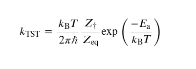
Transition state theory (TST) is based on statistical mechanics, explaining the elementary step reaction of slow thermal processes on a hypothetical “dividing surface” separating reactant and product regions of phase space. The conventional TST is based on a potential energy surface with a saddle point between the reactants and the products, where a transition state is a plane determined by normal coordinate analysis of small vibrations around the saddle point. In other words, the plane referred to here is obtained by minimizing displacement along the reaction’s normal coordinate. (112) The conventional TST valid at relatively low temperatures and in higher temperature saddle point regions may no longer control the reaction rate. (113) Therefore, the generalized transition state is more significant in such scenarios. According to TST, the rate constant at temperature T is defined as
(1)
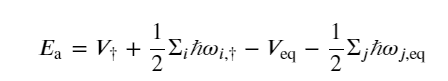
where kB and ℏ are the Boltzmann and reduced Planck constants, respectively, Z† is the partition function of the transition state without the contribution of the reactive mode, Zeq is the total partition function of the reactant state, and Ea is the activation energy defined as
(2)
where the frequency ωi,r corresponds to the square root of the ith positive eigenvalue of the Hessian of the potential energy surface evaluated at state r.
TST has several applications including the ability to predict the temperature and time dependence of defect nucleation, (114) rate constants analysis for intersystem crossings, spin-forbidden reactions, and spin-crossovers in large complex systems. (115)
3.1.1. Harmonic Transition State Theory
The application of TST is challenging due to the complexity of the equation for the rate constant (k). (114) This complexity in eq 1 for k was simplified by Vineyard (116) by introducing quadratic approximations to the energy surface around the critical points, hence giving harmonic TST (HTST) approximation. (116,117) Generally, the chemical reaction proceeded through a minimum energy path (MEP) as illustrated in Figure 3, and this path is connected over saddle points (where the most probable transition states are located) in the potential energy terrain. Figure 4 depicts the terrain of potential energy, where the initial and final configurations are separated by a hyperplane passing through a first-order saddle point on the energy ridge. Here, the hyperplane normal is pointed toward the direction of the unstable mode, the eigenvector of the Hessian matrix along which the saddle point is a maximum. (118) In some reactions, the second-order saddle points may occur above the first-order saddle points on the ridge, relevant to the fact that a particular transition mechanism and a certain product state are associated with those first-order saddle points. For a reaction, the MEP is extrapolated by advancing each degree of freedom of the system in such a way that the energy is minimal with respect to all degrees of freedom normal to the path. Further, MEPs are not unique for a given initial and final configuration. For a first-order saddle point (SP), at each point on the MEP, the energy is at a minimum with respect to all normal directions and maximum along the MEP. (119) The global maximum energy of the first-order saddle points refers to the activation energy for the reaction.


Vineyard’s approach in HTST, in line with TST, assumes that thermodynamic functions can also be defined at the saddle points. Further, the theory holds good particularly for solids at relatively low temperatures. This temperature approximation is fulfilled through the assumption that the energy difference between the second saddle point and the transition state shall be larger than kBT, i.e.,
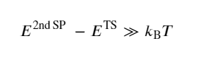
(3)
hence the rate of a chemical reaction in HTST is given as
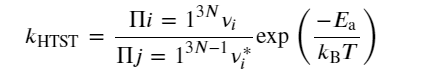
(4)
where νi are vibrational frequencies of a hopping atom at its equilibrium position prehop and νi* are the two real vibrational frequencies at the static saddle point. Further, HTST treatment on diffusion obeys first-order kinetics and agrees with the empirically observed Arrhenius expression for the temperature dependence of the rate constant. (120)
HTST is subjected to quantum mechanical corrections in certain circumstances. For instance, at very low temperatures, one has to consider the zero point energy of the vibrational ground state. Otherwise, this may cause an underestimation of the activation energy. (121) Also, based on the nature of the system, one may expect the tunneling from the reactant configuration to the final product configuration, especially when the barrier potential is thin. Neglecting the tunneling effect may result in an underestimation of the activation energy. (122) Similarly, replacing the classical partition function with their quantum mechanical analogs for the harmonic vibrations of the system can also influence the results of the rate constant. (120)
3.1.2. Nudged Elastic Band Theory
Finding the MEP is based on connecting the initial and final configurations of the reacting species through a number of transition configurations (known as images in NEB calculations). According to the plain elastic band method (PEBM), these transition states are assumed to be connected over a hypothetical spring of springs of zero natural length (chain of states) in the potential terrain; optimizing the spring forces with respect to the intermediate images while keeping the end point images yields the MEP. (123) In PEBM, the effective force acting on the ith image in the two-dimensional London–Eyring–Polanyi–Sato (LEPS) potential (124) is expressed as
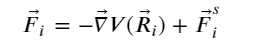
(5)
where F⃗is is the spring force defined as
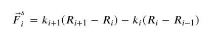
(6)
where k is the spring constant between pairs of images. However, the plain elastic band scheme suffers from the corner-cutting problem and thus overestimates the saddle point region in the terrain.
Since the PEBM is weak in most of the cases in predicting the MEP, Jónsson et al. (123) introduced a modified version, known as the nudged elastic band (NEB) approach. In this method, the spring force acting on the ith image in the same potential terrain is modified in such a way that the component of force acting on the image along the MEP’s local tangent (parallel) component and its perpendicular one are considered instead of the net force. The local tangent is expressed as
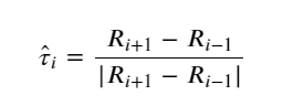
(7)
And, the spring force, F⃗iNEB, becomes
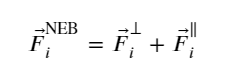
(8)
where
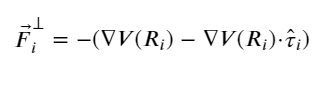
(9)
and
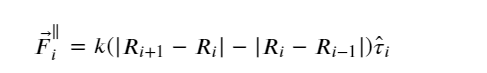
(10)
In short, the parallel component of the true force and perpendicular component of the spring force is projected out while minimizing the effective elastic force.
The NEB approach has been further improved by Henkelman et al. (125) on introducing a climbing image algorithm for an accurate estimation of the local tangent, thereby mitigating the problems with kinks on the elastic band in certain reactions. They also mentioned a new strategy where the NEB approach is combined with the dimer method for minimizing the computational effort in the estimation of the MEP approach. (126,127)
Furthermore, the NEB approach has been improved by Zhu et al. (128) for finding the SPs of the stress-assisted, thermally activated dislocation process in FCC metals. (129) This modification is known as free-end NEB, which is efficient particularly when the MEP is distorted by a high load, such that SPs come close to the initial state. This is implemented by cutting short the elastic band and allowing the end of the shortened band to move freely on the potential energy surface close to the initial state. (128)
3.2. General Modes of Ionic Transport through the SEI
The thickness of the SEI and crystallography of constituent components play a vital role in the ionic transport through the SEI. The ionic transport properties of Li-containing compounds in the nanoscale are significantly different from those measured in the bulk. (130) An electrochemical impedance spectroscopy study conducted by Guo and Gallant (131) showed that the ionic conductivity and diffusivity of Li2O on Li are several orders of magnitude higher than the reported values obtained using bulk pellet measurements. They argue that this difference is attributed to the dramatically different chemical, ionic, and microstructural environments in the SEI. Similarly, studies of Soto et al. (29) claim that the ionic size of chemical species is crucial in the transport properties. They affirm that Li ions tend to diffuse through an interstitial mechanism in Na-based SEI structures due to the smaller size of the Li ions relative to the sodium ions. While being so, the Na ions prefer a concerted exchange mechanism in Li-based SEI structures.
The major diffusion mechanisms in the SEI components include concerted exchange, knock-off, and direct hopping. (29) In a general notion, these diffusions take place through vacancy and interstitial defects. (130) In detail, the concerted exchange is a special type of diffusion with no defects involved, and this is a dominant mechanism by which substitutional atoms diffuse in semiconductors. In concerted exchange, atoms move through a set of configurations in such a way that, for energetic reasons, at any stage the number of broken bonds as well as distortions are kept at a minimum. (132) Direct hopping or an “interstitial mechanism” means that an interstitial atom diffuses through lattice interstitial spaces without displacing lattice atoms. (133) Alternatively, if the interstitial atom displaces a neighboring lattice atom into an adjacent interstitial site then it is known as a “knock-off or interstitialcy mechanism”, and this mode of diffusion is quite common in ionic crystals. (133) These kinds of diffusions mainly occur through grains, generally known as bulk diffusion.
Since the inorganic sublayer of the SEI is a polycrystalline material, the ionic transport also takes place through GBs. (134) It is well established that Li-ion diffusion along the GBs is orders of magnitude faster than bulk diffusion through the grains (or the lattice). (135) Furthermore, a quantum chemistry-based many-body polarizable force field study conducted by Borodin, Smith, and Fan states that Li ions migrate through the SEI as though they were dissolved in a liquid of polar–ionic species. (136)
Most of the previous studies about ionic transport consider the SEI as a homogeneous medium rather than a heterogeneous mosaic-like medium. However, a model developed by Shi et al. (25) investigated the diffusion as two distinct parts for organic as well as inorganic layers. They concisely summarized that diffusion through the outer inorganic layer follows Fick’s laws, and the diffusion through the inner organic layer needs further investigation. Their model considers the inner layers composed of Li2CO3, but in fact, the inner layer also has other inorganic components in a considerable proportion as mentioned earlier.
Crystalline defects in the SEI components also have an imperative role in Li-ion diffusion. A concise overview of the most likely types of defects along with their associated diffusion mechanisms and activation energies for the major components of the inorganic sublayer has been provided in Table 2. It is well understood that defects enhance the ionic conductivity in crystalline materials by creating an increased concentration of vacancies and interstitial spaces. (137) At a given temperature, the internal equilibria of defects depend upon the atomic structure of the defects and the electronic band structure of the material. (138) The defects’ concentration varies with respect to the environment (here, the electrode) in which the inorganic layer is in thermodynamic equilibrium. It has also been reported that the concentration of the defects is also related to the voltage of the electrode with which the SEI is in contact. (139) Since defect formation plays a significant role in ionic transport, analysis of the defect formation energy and associated migration properties is important to understand the whole dynamics of ionic transport. In the following paragraphs, we have summarized possible defects with their properties and associated mechanisms of ionic transport through the major components of the SEI.
Table 2. Major Inorganic SEI Components along with Their Most Probable Defects Types, Diffusion Mechanism, and Migration Barrier
| SEI inorganic components | major defects | diffusion mechanism | migration energy barriers (eV) |
|---|---|---|---|
| LiF | Schottky pairs (140) | vacancy diffusion (29) | 8.17 |
| Li-ion vacancies (140) | concerted exchange (29) | 4.07 | |
| knock-off (29) | 6.1 | ||
| direct hopping (29) | 5.96 | ||
| Li2CO3 | Li-ion interstitials (25) | knock-off | 0.67–1.07 |
| Li-ion vacancies (25) | direct hopping | 0.92–1.32 | |
| vacancy diffusion (29) | 0.28 | ||
| concerted exchange (29) | 1.6 | ||
| Li2O | cation–Frenkel pairs (141) | knock-off | 1.1–2.5 |
| vacancy defect | 0.3–1.0 (142) | ||
| interstitial defect | 0.6–1.2 (142) | ||
| LiOH | vacancy defect | knock-off | 0.20 (62) |
| interstitial defect |
3.2.1. Lithium Fluoride
LiF is a stable component of the SEI that forms from electrolytes containing fluorine. It is one of the major components of the SEI along with other components─Li2O, LiOH, and Li2CO3. The stability property of LiF has been utilized for generating long-lasting interphases because it forms highly stable interfaces with the electrolyte. (143) LiF is also well known for its temperature tolerance. For that reason, using it as a major component of the SEI improves the high-temperature cycle performance of the battery. (144) It has been reported that LiF can be formed through decomposition of the salt such as LiPF6 (145−147) and LiTFSI, (148,149) additives such as fluoroethylene carbonate, or via reactions involving trace HF. (146,150,151) Cao et al. (55) says that it is challenging to predict the mechanism of LiF formation. Given the popular precursors LiPF6 and carbonates, they concluded that formulation of LiF at 1.5 V proceeds through a concomitant occurrence of both direct PF6– anion reduction and electrocatalytic transformation of hydrogen fluoride (HF).
Most of the diffusion studies in LiF were performed using the first-principles-based methods. These studies are performed in two parts: (1) the concentration of defects in the SEI in contact with electrodes and (2) the transport of the dominant defects (e.g., Li vacancy). (140) Pan et al. (140) have correlated the chemical potential of lithium with the voltage of the electrodes. This is a promising approach to model ionic transport as defect properties are linked to an electrochemical parameter. Furthermore, Pan et al. (140) analyzed the ionic conductivity of a total of 17 possible native defects with their relevant charge states in LiF and concluded that the main defect type in the intrinsic region was a Schottky pair and in the p-type region was Li-ion vacancy (here, the regions are defined to describe the main defect reactions with different electrodes). They have also conducted a fruitful comparison between lithium and sodium ions in terms of the defect properties in their respective SEI component and found that the energy required to create defects in LiF is the lowest when Na ions replace Li ions due to the smaller size of the lithium ion when compared to the sodium ion. Besides that, lithium ions in Na-based SEI components prefer a mechanism involving the migration of the interstitial ion through the knock-off or direct-hopping mechanism.
In 2018, Soto et al. (29) reported in their NEB study on defects that the diffusion barrier of the positively charged F vacancy is 0.69 eV and the negatively charged Li vacancy ranges from 0.57 to 0.60 eV in LiF. In the same work, the authors also mentioned that Li-ion migration in LiF is much higher (0.73 eV) when compared to Li2O (0.15 eV) and Li2CO3 (0.23–0.49 eV). This finding has also been verified in another work by Zheng et al. (62) in which they claim that the key reason behind this fast transport phenomenon is because similar ions are being localized in the surrounding environments between the initial state and the transition state during the diffusion process. The Li-ion diffusion through bulk LiF also points toward a higher diffusion barrier as shown in Figure 5a with vacancy-assisted mode as the favorable mechanism of diffusion.

The energy profile of the diffusion barrier for various mechanisms of sodium-ion diffusion through LiF is given in Figure 6a. Among the given mechanisms mentioned in the figure, concerted exchange between two lattice positions has the lowest activation energy (4.07 eV). However, this mechanism requires a significant change in the structure, resulting in a migration barrier of 3.32 eV. Due to this high barrier, it can be inferred that Na diffusion through LiF is not very likely compared to its diffusion through NaF. Also, for the same diffusion process, the direct-hopping mechanism was found to have the lowest energy barrier (0.38 eV), whereas the knock-off mechanism had a slightly higher barrier (0.52 eV).

When examining the ionic conductivity of LiF, a strong correlation to the electrochemical environment can be deciphered. For instance, the ionic conductivity of LiF is reported to be approximately 10–31 S cm–1 when it is in contact with a negative electrode, and it increases to 10–12 S cm–1 on a positive electrode. (140)
When investigating the ionic conductivity of LiF, a notable correlation with the electrochemical environment becomes apparent. Specifically, it has been observed that the ionic conductivity of LiF is approximately 10–31 S cm–1 when it is in contact with a negative electrode, and this value increases to 10–12 S cm–1 when it is in contact with a positive electrode. This finding highlights the significance of the electrochemical conditions in which LiF operates and emphasizes the importance of understanding the diffusion properties based on the surrounding media in order to optimize the performance of a LiF-based SEI.
An NEB study on bulk LiF suggests that lithium vacancy-assisted diffusion is difficult to happen at room temperature due to the higher migration energy barrier (0.729 eV). (152) Also, this migration barrier is much higher than the lithium-ion migration barrier in graphite (0.48–0.49 eV). (153)
LiF is well known for its insulating properties when it is in an SEI environment. Theoretical studies have shown that crystalline LiF has a wide band gap of 10.8 eV, which effectively prevents electronic tunneling through its lattice. Experimental measurements, however, have shown the band gap to be even wider at 14.1 eV. The electronic density of states depicted in Figure 7 provides further evidence of this insulating behavior. These findings highlight the importance of the unique electronic properties of LiF, particularly in the context of its presence in LiF. (62,140)

3.2.2. Lithium Carbonate
Lu and Harris (27) provided a brief summary of their TEM, HRTEM, and XPS studies, outlining the presence of Li2CO3 as one of the stable components of the SEI. They noted that the inner inorganic layer is dense and that the primary component is crystalline monoclinic Li2CO3. In a separate study, Shi and Lu reported the presence of Li2CO3 on both the cathode and the anode surfaces and suggested that Li-ion interstitials are the primary carriers of Li ions in the voltage range of 0–0.8 V. (25)
In a follow-up study utilizing DFT calculations, they found that excess Li-ion interstitials (below 0.98 V) and Li-ion vacancies (above 3.98 V) are the primary diffusion carriers in Li2CO3. Both carriers are equally dominant within the voltage range of 0.98–3.98 V. Additionally, they observed that Li+ interstitials are the dominant diffusion carriers in Li2CO3 on the anode (graphite), whereas Li+ vacancies play this role on the cathode (NCA).
A study conducted on bulk Li2CO3 that formed on a graphite anode identified five crystallographically distinct migration pathways generated on a vacancy defect. The study showed that the lowest energy barrier is approximately 0.227 eV, while the highest energy barrier is approximately 0.491 eV. This indicates that Li ions can rapidly diffuse through the Li2CO3 compound when vacancies are present in the lattice. Additionally, Figure 5b in the study supports this finding, displaying a migration barrier of 0.21 eV. The study also determined that direct hopping is the energetically favorable mechanism for diffusion in bulk Li2CO3.
The energy profiles for various mechanisms of diffusion of sodium ion through Li2CO3 are given in the Figure 6b. The said figure depicts the knock-off mechanism as an easy way of ionic diffusion through Li2CO3 with less energy expenditure. Further, the underlying mechanism of the interstitial diffusion is a knock-off mechanism, which is controlled by the coordination number with oxygen anions rather than by the size of the open channels in Li2CO3. (25) This mechanism generally applies to ionic conductors with isolated polyhedral anions or layered tetrahedral networks. (25) In addition to this, Iddir and Curtiss (154) reported that vacancy-mediated Li-ion diffusion is negligible when compared to the interstitial Li-ion diffusion along the (010) plane of Li2CO3 through which an easy migration occurs with an energy barrier of 0.28 eV.
Although Li2CO3 contributes to the strong mechanical rigidity of the SEI with a mechanical strength range of 192–330 MPa, its effect on Li-ion transport is still uncertain. (155) Some studies suggest that crystalline Li2CO3 is a typical Li-ion conductor. (156) A previous study by Zhang and colleagues demonstrated that doping Li2CO3 with Li3PO4 can enhance its ionic conductivity for temperatures up to 400 °C. (157) However, in 2004, Zhuang’s research group showed strong evidence of particle isolation that resulted from the formation of Li2CO3 on LiNi1–xCoxAlyO2 (NCA) particles. (158) In their study, some NCA particles could not be lithiated/delithiated after the surface was covered with Li2CO3; however, it is not clear if this was a result of Li2CO3 blocking Li-ion transport or electronic tunneling. (159)
Furthermore, Li2CO3’s lithiophobic nature is still evident in certain garnet composite electrolytes such as PLLA electrolyte, where removing Li2CO3 from its continuous conductive interlayers leads to higher lithium-ion carrier concentration and faster lithium-ion transport. (160)
Meanwhile, the electronic band gap data of Li2CO3, which is theoretically 7.07 eV and experimentally 7.5 eV, indicates that it exhibits electronic insulating behavior. (21)
3.2.3. Lithium Hydroxide
LiOH has a unique tetragonal layered-like crystal structure with the P4nmm space group, with lithium ions occupying the central sites of the layered-like structure while the OH– groups are vertically connected with the layer structure. Electrically, LiOH is an insulator with a band gap of 5.481 eV. It is formed in lithium-ion batteries through the reaction between LiPF6 salt and trace amounts of moisture in the battery electrolyte and can also form from the reaction between Li2O and water. (161,162) The presence of LiOH in the SEI is well established, and it is primarily found in aged electrodes, likely due to the reaction of water with the methoxide and oxalate. (163) The presence of LiOH in the SEI plays a critical role in forming a protective layer on the surface of the anode, which prevents further electrolyte reduction and degradation of the electrode material.
Research has shown that bulk-phase LiOH has the lowest migration barrier, estimated at 0.20 eV, and tends to prefer diffusion via a knock-off mechanism (as illustrated in Figure 5c). This mechanism is initiated by the diffusion of the Li ion located at the interstitial site along the [001] direction while simultaneously knocking off an existing Li ion from the lattice site, leading to the transition state. Compared to other bulk diffusion mechanisms, LiOH also exhibits faster diffusion (with a diffusion coefficient of 9.236 × 10⁻⁶ cm2 s–1 at 300 K), similar to that observed in LiF. Furthermore, adsorption studies using Bader charge and differential charge density have indicated a significant charge transfer between the Li adatom and LiOH, which is greater than those observed in LiF, Li2CO3, and Li2O. This supports the bonding nature between the lithium and the oxygen atoms in LiOH. (62)
3.2.4. Lithium Oxide
Li2O is an active participant in the SEI with an antifluorite crystal structure, which forms when low-voltage anodes come into contact with solid or liquid electrolytes containing oxygen. (164) Li-ion migration via knock-off, direct-hopping, and vacancy-assisted methods has been reported in Li2O, and the corresponding energy profile is illustrated in Figure 5d. The dominant intrinsic defects in Li2O are cation–Frenkel pairs, which consist of an interstitial Li+ and a negatively charged vacancy, according to Chadwick et al. (141) Ionic migration in fluorite-structured materials is typically associated with thermally induced Frenkel-type disorder at temperatures below the melting point. (165) The ionic conductivity of Li2O is therefore moderately low (∼10–12 S/cm at room temperature), similar to that of Li2CO3 (∼10–8 S cm–1), but it can be increased through appropriate doping. (142,166) A change in the activation energy is consistently observed at 650–800 °C, and conductivity is insensitive to doping beyond this temperature region. However, Lorger et al. (142) reported that the ionic conductivity in Li2O is relatively insensitive to doping for a temperature range of range 250–900 °C due to the low solubility of most plausible dopants. In their defect chemical model of Li2O, they also mentioned that the electronic conductivity is much lower than the ionic conductivity, at least under oxidizing conditions, which helps reduce the growth rate of the SEI layers over anodes. They concluded the findings by putting forward a controversial fact that while ionic transport is too slow in bulk Li2O, the Li2O present in the SEI exhibits a faster ionic conductivity. This fact could stem from the collective action of other SEI components and the presence of more GBs, where faster Li-ion transmission occurs.
In more detail, the faster diffusion of vacancies in Li2O may result from lithium vacancy-assisted migration along the cubic edges where Li atoms are located at the corners of the simple cubic structure, as illustrated in Figure 8. The activation energy for edge-oriented migration (0.152 eV) is much lower than that for migration over the face or body diagonals. (152) In addition, the vacancy is located in an octahedral void surrounded by six other lithium atoms (three on top and three on bottom), enabling vacancies along the cubic edges to diffuse rapidly in a three-dimensional network.

In a related study, Guo and Gallant (131) investigated the ionic migration through the solid-state Li2O interface on the lithium cathode end. Their research found that the formation temperature significantly influences the transport parameters of Li2O due to the emergence of larger grains and the decrease in grain boundary density resulting from the higher reaction temperature. Furthermore, they reported that the ionic conductivity and diffusivity of Li2O on lithium are several orders of magnitude higher than the values obtained through bulk pellet measurements. This observation is similar to that of Li2O present in the SEI formed on the anode.
3.3. Factors Affecting the Ionic Migration in the SEI
3.3.1. Crystallographic Planes
The formation of ionic migration channels in the inorganic sublayer of the SEI is greatly affected by the crystallographic planes of the constituent components and their corresponding directions. Typically, planes with lower surface energy are formed. As a result, the grain boundaries of components in the inorganic sublayer typically consist of planes with the lowest surface energy. Furthermore, crystal planes with a larger specific surface area and hence have more exposed planes are beneficial for facilitating rapid transport of Li ions. (167) Additionally, the formation of the SEI is influenced by the surface energy and the stability of the cathode/anode material. (168) Studies have shown that certain planes ({111} and {110}) of a Mn spinel cathode with a truncated octahedral shape exhibit enhanced Li-ion diffusion, resulting in improved cycling properties. (169−171)
Another notable correlation between ionic migration with planes and directions has been demonstrated in a study conducted by Shi et al. (159) According to the study, the diffusion of Li+ and Li– in Li2CO3 results in the formation of a lithium Frenkel pair when their distance is approximately between 3 and 5 Å on the same (100) plane. The motion of the interstitial and vacancy in the formed Frenkel pair is highly correlated along [010] in the (001) plane. Another DFT-based study by Iddir and Curtiss (154) found that the activation energy for Li-ion diffusion across the plane of Li2CO3 was 0.60 eV, which is higher than that for the diffusion along the open channels (0.28 eV) in the [010] directions. This indicates that the diffusion of Li ions across the plane of Li2CO3 is slower compared to the diffusion along the open channels. Their subsequent research on the same topic revealed that the energy barriers for the Li+ ion to hop through the open channel and for a neutral Li vacancy to move along [001] are 0.28 and 0.23 eV, respectively. Islam and Bredow (172) conducted a study that showed a similar trend in other SEI components as well. According to their investigation, the most likely migration pathway for Li+ in Li2O on its (111) plane is a zigzag pathway, rather than a straight line along a direction parallel to the surface plane, with an activation energy of 0.25 eV.
For further reference, the surface energies for selected planes of various SEI components have been listed in Table 3. All of the data in Table 3 have been validated with VASP to check the consistency of the data. In addition to this, the surface energy of unexplored components has also been added to the table. The trend in the table shows that the most stable crystal surface for LiF, Li2CO3, and LiOH is (001), and it is (111) for Li2O. Also, it is clearly visible that the surface energy of slabs with nonzero dipole terminations (for example, the (111) surface of LiF, (100) surface of Li2O, and (001) surface of LiOH) is higher when compared to the slabs with zero dipole symmetric terminations.
Table 3. Surface Energy of All Possible Orientations of the Crystallographic Planes of Reported SEI (Inorganic) Components
| SEI components | surface orientation | surface energy per atom | theoretical─DFT (meV/Å2) | experimental (meV/Å2) |
|---|---|---|---|---|
| LiF | (001) | 18.97 | 20 (173) | |
| (110) | –4.82 | 46.09 | 49 (173) | |
| (111) | 56.40 | 55 (173) | ||
| Li2CO3 | (001) | PSa | 11.23 (174) | |
| (110) | –6.37 | PSa | 13.47 (174) | |
| (110) | PSa | 35.57 (174) | ||
| Li2O2 | (0001) | PSa | 41 (175) | |
| (1100) | –4.86 | PSa | 52 (175) | |
| (1100) | PSa | 105 (175) | ||
| Li2O | (100) | 74.78 | 75 (176) | |
| (110) | –4.78 | 57.00 | 56 (176) | |
| (111) | 29.25 | 30 (176) | ||
| LiOH | (001) | 160.28 | 13 (177) | |
| (100) | –5.09 | 21.46 | 16.22 (177) | |
| (111) | 30.35 | NA | ||
| LiN | (100) | 127.23 | NA | |
| (110) | –3.73 | 40.51 | NA | |
| (111) | 38.22 | NA | ||
| Li2S | (100) | PSa | 52 (178) | |
| (110) | –4.07 | 32.60 | 33 (178) | |
| (111) | 22.52 | 21 (178) |
a
Polar surface termination: The conventional method used to calculate surface energy is not efficient for polar surfaces because of its inability to decouple the two nonequivalent surfaces generated. Polar surface termination can be treated as compensating for the charge by capping with foreign atoms to satisfy the electron counting rule, hence nullifying the polarity of exposed surfaces.
3.3.2. Grain Boundaries
As described in section 3.2, the Li-ion transport through GBs is faster than migration through lattice spaces. In a study on GBs conducted by Chen et al., (106) it was shown that Li3N-based SEI films rich in GBs on the surface of Li metal exhibit enhanced rate performance and long-term cycle stability without dendrite formation. Similar to this, work on the La–LiF interface suggests that the GB with a stable vacancy structure and a smaller transport energy barrier facilitates efficient Li-ion migration in the interface system. (179) Another remarkable comment on this is from the work of Zhang et al., (180) in which they state that abundant heterogeneous GBs among LiF, LiNxOy, and Li2O contribute to uniform and rapid diffusion of Li ions through the SEI, which guarantees uniform lithium deposition.
A recent work of Ramasubramanian et al. (181) demonstrated the Li-ion transport through GBs of Li2O, LiF, and Li2CO3, in which they clearly mentioned that a faster lithium diffusion occurs through numerous open channels formed by the GBs. Particularly, their DFT studies showed that the fastest lithium diffusion rate is observed in the heterogeneous LiF/Li2O GB compared to the homogeneous LiF/LiF and Li2O/Li2O GBs. In terms of electronic transport, their studies suggest that achieving a dense SEI structure with well-ordered grain boundaries (GBs) and sharp interfaces is essential to maintain electronic passivity, which in turn helps suppress dendrite growth and electrolyte reduction. (182)
4. Conclusions and Future Perspectives
Formation of the SEI is influenced by the chemistry of the electrolytes and additives and the surface chemistry of electrodes along with other parameters such as temperature, voltage, and current density in the first few cycles of the battery. A retrospective outlook on previous studies encapsulates that the SEI is a bilayered mosaic-type structure composed of thick porous organic and densely packed inorganic grains. The organic layer is a result of the reduction of the electrolyte at the electrode surface, and its composition and properties are highly dependent on the electrolyte used. Similarly, the composition of the inorganic grains is primarily affected by the type of electrode material and electrolyte used as well as the additives added to the electrolyte.
Ionic transport through the SEI is a function of several parameters, such as the chemical composition of constituent components, the thickness of the layer, defects, and impurities in individual components, the presence of GBs, and the surface properties of the electrode. The transport of Li ions in the SEI follows two distinct mechanisms through the two aforementioned layers. According to the literature, the organic layer of the SEI close to the electrolyte is often considered thick and porous, leading to Fick’s laws-mediated diffusion dynamics. In contrast, the ionic transport mechanism through the inorganic layer is more complex and typically occurs through defects in grains and over GBs of the constituent components. Based on our review of the literature in this field, it has been concluded that the inorganic layer of an optimized SEI is primarily composed of grains of LiF, Li2O, LiOH, and Li2CO3. Table 2 provides a brief summary of the most likely diffusion mechanisms observed in these inorganic components. Furthermore, it is crucial to thoroughly consider the inorganic layer of the SEI to prevent dendrite growth from the electrode’s surface. This sublayer has a significant impact on the battery’s cycling performance as it is positioned on the surface of the electrode.
Formation of the SEI occurs in a dynamic electrochemical environment, which increases the possibility of defects in the constituent components of the inorganic sublayer. As a result, the vacancy-assisted diffusion mechanism is dominant in this sublayer. Through vacancy-assisted diffusion, Li ions are diffusing without significant distortions in the lattice while neighboring atoms are relaxing. When it comes to other modes of diffusion, we see a common trend of the dominance of Li+ interstitial-mediated diffusion when open channels are available in crystal systems. This type of diffusion requires interstitials with lower energy to be available in the crystal system. A study by Shi et al. (25) sheds light on this fact; they found that the higher the coordination number of the excess interstitial Li+ with O ions, the lower the energy of the interstitial structure; this is more evident in Li2CO3 and Li2O crystals which facilitate faster Li-ion transport.
In terms of the major components present in the inorganic layer of the SEI, LiF exhibits a wider band gap, indicating its electronic insulating properties. However, it also possesses a higher energy barrier for Li-ion diffusion, leading to slower transport through the lattice. Despite this, the stability of LiF makes it a more favorable component when compared to others. Similarly, the bulk-phase Li2CO3 exhibits promising Li-ion transport, and its role in Li-ion transport through the grain phase is dependent on various parameters such as the type of electrode and the chemistry of other associated inorganic components. However, its transport properties are moderate in comparison to Li2O. Nevertheless, due to its low-energy surface, particularly (001), and chemical stability, it can serve as a potential component in the inorganic sublayer of the SEI. When it comes to Li2O, its ionic transport is faster due to its low diffusion energy barrier. Although its electronic band gap is narrower than that of LiF and Li2CO3, it still exhibits electronic passivity within the layer.
A thorough analysis of electronic passivity of the SEI indicates that the lithium vacancies present in inorganic components create holes, which are typically contributed by the nearest neighboring O or F atoms. These holes are highly localized to the nearest neighbors (O for Li2O and Li2CO3 and F for LiF), which results in minimal contribution to the electronic conductivity. However, certain intrinsic defects and tunneling may permit a negligible number of electrons to pass through the SEI. (152)
Based on the analysis, it can be inferred that the above-mentioned inorganic components display chemical and thermodynamic stability, thereby conferring structural robustness to the SEI. Nonetheless, their mechanical stability is inadequate to withstand the volumetric pressure engendered by the matrix of silicon–graphite composite-based electrodes.
Further, it is evident that grain boundaries play a crucial role in the ionic transport of the SEI. Numerous studies on the SEI have reported that Li-ion diffusion through GBs is significantly faster compared to lattice diffusion. Among the various inorganic component configurations, LiF/LiF, Li2O/Li2O, and LiF/Li2O are the most stable. The heterogeneous LiF/Li2O GB configuration favors the most rapid Li-ion transport. (181) Apart from this, several factors such as potential gradient, operating temperature, adsorptive properties of the electrode, impurities in the local matrix, and associated defects can also influence the Li-ion transport across the SEI.
It is apparent that by appropriately designing the SEI, the volume expansion occurring during intercalation can be somewhat alleviated. Recent investigations on the use of an artificial SEI to reduce volume expansion and preserve the integrity of silicon-based electrodes exemplify this. Regarding cathode materials, a significant challenge is the formation of dendrites, which can result in the thermal runaway of the battery. However, this can be prevented by creating a mechanically stable SEI. It has been observed that dendritic growth of lithium often occurs along the grain boundaries and defective sites within the electrode. However, it is important to consider that these same GBs and defects can serve as favorable channels for rapid ionic transport. (183) From this fact, we can infer a subtle correlation between ionic transport channels and dendrite growth.
The majority of studies investigating the ionic transport properties of SEI have been focused on the inorganic layer. Consequently, the constituent components of this sublayer have been extensively studied in the past decade. However, the individual components of the organic layer and their role in Li-ion transport through this sublayer have not been thoroughly explored, likely due to the diverse chemical nature of the organic sublayer, which is influenced by the properties of the electrolyte and additives utilized. A greater focus on the organic portion of the SEI layer could enhance our overall understanding of Li-ion transport through the SEI. Thus, a better comprehension of the organic sublayer of the SEI could have a significant impact on our broader understanding of Li-ion transport through the SEI.
In summary, the performance of LIB is significantly influenced by the ionic transport mechanism through the solid electrolyte interphase. The SEI layer guides active lithium ions to the electrode, and intercalation largely depends on the chemical composition of the SEI. Additionally, the SEI plays a crucial role in ensuring the uniform distribution of active lithium ions to the electrode surface, which is essential for efficient intercalation and higher capacity of the LIB. A nonuniform lithium-ion distribution may lead to dendrite formation and decreased battery performance.
【Article link】