Fanjue WenFanjue Wen
Key Laboratory of Hydraulic Machinery Transients, Ministry of Education School of Power and Mechanical Engineering, Wuhan University, Wuhan, 430072, China
More by Fanjue Wen, Shuai Cao, Xin Ren, Yuliang Cao, Xinping Ai, and Fei Xu
Cite this: ACS Appl. Energy Mater. 2022, 5, 12, 15491–15501
Publication Date:December 5, 2022.
Abstract
Trimethyl phosphate (TMP) is the most promising safe solvent for lithium-ion battery (LIB) electrolyte because of the nonflammability, oxidation stability, and low cost, but its application is hindered by incompatibility with the graphite anode. Herein, nonflammable electrolytes with ordinary concentration (1 mol L–1) are designed for graphite/LiNi0.8Co0.1Mn0.1O2 (Gr/NCM811) LIBs with TMP/2,2,2-trifluoroethyl methyl carbonate (FEMC) binary solvents. Stable cycling of the Li/Gr half cells with high capacity is achieved via modulation of the Li+ solvation structure. A dual-salt strategy of lithium hexafluorophosphate/lithium difluoro(oxalato)borate is further used to realize the high performance of the Gr/NCM811 full cells. More significantly, the functions and relationship of Li+ solvation structure and electrode/electrolyte interphase are elucidated. Li+ solvation structure and interphase are respectively the thermodynamic and kinetic factors for the side reactions of the electrolyte occurring at the electrode/electrolyte interphase, which should be considered comprehensively in the design of electrolytes for high-energy density LIBs.
1. Introduction
The safety issue of lithium-ion batteries (LIBs) is becoming increasingly prominent with the boosting of their energy density. (1−3) This is mainly due to the flammability of the electrolyte, which causes combustion and even explosion. Phosphate esters are promising substitutes for carbonate solvents to ensure the safety, (4−6) among which trimethyl phosphate (TMP) is the most prominent because of its nonflammability, oxidation stability, and low cost. (7−9) However, TMP tends to be over-reduced at or cointercalated with Li+ into the graphite anode, resulting in considerably low compatibility, making it only used for high-concentration electrolytes (HCEs). (10,11) With coordination of the anions with Li+ cation in the solvation structure, HCE not only improves the reduction tolerance but also enables anions to participate in the formation of solid electrolyte interphase (SEI), thus improving the compatibility with graphite. For example, it has been demonstrated that the Li/graphite (Li/Gr) half cells using HCE of lithium bis(fluorosulfonyl)imide (LiFSI, 5.3 mol L–1):TMP (1:1.64 in mol) show a stable cycling. (10) However, the high viscosity and high cost seriously hinder the application of HCE. Localized high-concentration electrolytes (LHCEs) were later proposed, using noncoordinating solvent as diluent and manipulating the mole ratio of Li salt to strongly coordinating solvent, to regulate the anions entering the Li+ solvated structure at normal concentrations. (12−14) The LHCE strategy was also used for nonflammable LIB electrolytes, such as LiFSI (1.44 mol L–1):TMP-FEC (fluoroethylene carbonate)-TTE (1,1,2,2-tetrafluoroethyl-2,2,3,3-tetrafluoropropylether). The graphite/LiNi0.8Co0.1Mn0.1O2 (Gr/NCM811) full cell showed excellent cycling stability because the FSI– anion was introduced into the Li+ solvation structure of LHCE, and FEC additive was employed for SEI formation. (12)
Although the concentration and viscosity have been reduced and the ionic conductivity has been increased to a certain extent, there are still limitations in the current LHCE strategy. Using LiFSI is reasonable for HCE because of the high dissociation degree, high solubility, and good interphase compatibility. While for LHCE, the weak coordinating nature of FSI– impedes its participation in the Li+ solvation structure. Hence, LHCE can only be achieved by increasing LiFSI to a certain concentration and reducing the strong coordinating TMP solvent to a low proportion. For instance, FSI– could only be introduced into the Li+ solvation structure of the LiFSI:TMP-TTE electrolyte at a concentration higher than 1.0 mol L–1 (1.44 mol L–1). (12) Even though, an additive such as FEC is still demanded for a stable cycling of Gr/NCM811 full cell. Therefore, new strategies are needed to further reduce the Li salt concentration to a normal level (1 mol L–1), providing more freedom for the electrolyte design. More significantly, the Li+ solvation structure and electrode/electrolyte interphase, the two most important factors for the LIB electrolytes, have already attracted considerable attention. (15) However, previous studies either focused on solvation structure or interface, and an in-depth clarification of their roles and intrinsic relationship is still ambiguous. In case of a conflict between these two factors, a reasonable understanding of their functions is of great significance for the design of electrolyte and optimization of the cycling stability of LIBs. The double salt strategy is also an important method to improve the electrolyte. (16,17)
In the present study, nonflammable electrolytes with normal concentration (1 mol L–1) are developed for Gr/NCM811 LIBs, using TMP/2,2,2-trifluoroethyl methyl carbonate (FEMC) binary solvent and lithium hexafluorophosphate (LiPF6)/lithium difluoro(oxalato)borate (LiDFOB) dual-salt strategy. The nonflammability of the electrolyte was confirmed by exposure to fire. The Li salts act as both Li+ conducting agents and SEI formation components, which demand high (weak coordinating anions) and low dissociation degrees (strong coordinating anions), respectively. Apparently, it is difficult to meet the opposite requirements with one single salt. Hence, a LiPF6:LiDFOB dual-salt strategy is used herein. The DFOB– anion has excellent interphase properties and moderate coordinating ability, making LiDFOB a favorable SEI-formation Li salt. (18,19) Commercial LiPF6 is used as the Li+ conducting salt with the high dissociation degree and low cost. FEMC is selected as the diluent because of its high oxidation stability, nonflammability, low viscosity, and weak coordinating ability. (20,21) The performance of the Gr/NCM811 full cell was optimized with modulation of the Li+ solvation structure and SEI through a change of the Li salt species and TMP:FEMC solvent ratio. Furthermore, the functions of Li+ solvation structure and interphase and their intrinsic relationship were elucidated. The present study provides important insights into the understanding of Li+ solvation structure and electrode/electrolyte interphase, design of nonflammable electrolyte and cycling stability optimization of LIBs.
2. Experimental section
2.1. Synthesis
Electrolytes were prepared in an Ar-filled glovebox (Mikrouna, O2 and H2O < 0.1 ppm) using trimethyl phosphate (TMP, 98%, Energy Chemical), 2,2,2-trifluoroethyl methyl carbonate (FEMC, 98%, Aladdin), lithium hexafluorophosphate (LiPF6, 99%, DFD), and lithium difluoro(oxalato)borate (LiDFOB, 98%, D&B). TMP and FEMC were dehydrated with activated 3A molecular sieve prior to use. Each component was controlled according to the mole ratio. Fluoroethylene carbonate (FEC, 99.95%, DoDoChem) was used as the additive for some electrolytes.
The graphite electrodes were prepared by coating deionized water slurry containing graphite (COSMX), acetylene black (AB, Saibo), and binder with a mass ratio of 85:6:9 on Cu foil and dried under vacuum at 100 °C for 24 h. The binder was a mixture of carboxymethyl cellulose (CMC, COSMX) and polymerized styrene butadiene rubber (SBR, COSMX) with a mass ratio of 1:1. The LiNi0.8Co0.1Mn0.1O2 (NCM811) electrodes were prepared by coating N-methyl pyrrolidone (NMP, Energy Chemical, 99.5%, extra dry with molecular sieves) slurry containing LiNi0.8Co0.1Mn0.1O2 (NCM811, COSMX), Super P (SP, COSMX), and polyvinylidene fluoride (PVDF, COSMX) with a mass ratio of 8:1:1 on Al foil and dried under vacuum at 100 °C for 24 h. The loadings of the active materials were about 1.8 and 2.4 mg cm–2, respectively, for the graphite and NCM811 electrodes.
Electrochemical measurements of Li half cells were conducted with CR2032 coin type cells, using the graphite or LiNi0.8Co0.1Mn0.1O2 electrodes as working electrode, a Li foil as counter electrode, the prepared electrolyte (80 μL), and a Celgard separator (2325, diameter of 19 mm). Electrochemical measurement of full cells adopted graphite as anode and NCM811 as cathode under the same conditions. The active materials were matched according to 10% excess of the capacity of graphite. The battery assembly was carried out in the Ar-filled glovebox.
Galvanostatic cycling tests were conducted on battery cyclers (LAND-CT2001A). The voltage ranges of the Li/Gr and Li/NCM811 half cells were 0.01–2.0 V and 3.0–4.3 V, respectively. The voltage range of the Gr/NCM811 full cell was 3.0–4.3 V. The current densities were 50 mA g–1 for normal tests at 25 °C and 20 mA g–1 for the low temperature tests.
2.2. Characterizations
Ex-situ characterizations were conducted for the electrodes at different states. The coin cells were dissembled in the Ar-filled glovebox, and the electrodes were washed carefully with dehydrated dimethyl carbonate (DMC) and dried prior to the ex-situ characterizations. X-ray photoelectron spectroscopy (XPS) was recorded on Thermo ESCALAB 250XI. The morphology and elemental information were analyzed on scanning electron microscopy (SEM, FEI Quanta 200). Raman spectroscopy was obtained using a laser micro-Raman spectrometer with 532 nm excitation wavelength (Renishaw in Via, Renishaw). Fourier transform infrared (FTIR) spectra were collected by Thermo Scientific Nicolet iS50 FT-IR (attenuated total reflection mode) with 8 cm–1 resolution.
2.3. Computational Details
All computations were carried out with the Gaussian 16 software. (22) The B3LYP functional and 6-311G(d) basis set were adopted for all computations. (23,24) The DFT-D3 with BJ-damping was applied to correct the weak interaction to improve the calculation accuracy. (25) Orbital energy level analysis was performed by Multiwfn software. (26) The visualization of the orbitals was achieved using VESTA software.
3. Results and Discussion
3.1. Modulation of Li+ Solvation Structure (Thermodynamics)
The total mole ratio of the Li salts and solvents was fixed to 1:8 in the present study to ensure the Li salt concentration of 1 mol L–1. Attention was devoted to the compatibility between the electrolyte and graphite anode first because of the high oxidation stability and low reduction stability of TMP and FEMC. Four LiPF6 electrolytes with TMP:FEMC mole ratios of 4:4, 2.5:5.5, 2:6, and 1.6:6.4 were first used for the Li/Gr half cells (Figure 1a,b and Figure S1). As shown in Figure 1a,b, the first-cycle charge capacity increases with the increasing proportion of FEMC. The electrolyte of LiPF6:TMP:FEMC = 1:4:4 provides a negligible capacity (Figure 1b), while for the electrolyte of LiPF6:TMP:FEMC = 1:1.6:6.4, the Li/Gr cell exhibits a high reversible capacity (354.1 mAh g–1) and a perfect cycling stability (100-cycle capacity retention (CR) of 98.1% and a stable Coulombic efficiency of 99.7%, Figure S1a,b).

To explain this difference, FTIR (Figure 1c) and Raman spectra (Figure 1d) of these four electrolytes were measured to determine the Li+ solvation structures. In the FTIR spectra (Figure 1c), the C═O peaks of free and Li+-coordinated FEMC molecules are respectively at 1770 and 1727 cm–1. (27,28) It is observed that the peak intensity of the Li+-coordinated FEMC (Li+-FEMC) increases with increasing FEMC proportion, indicating more FEMC molecules participating in the Li+ solvation (coordinated with Li+). While for PF6–, the ratios of the free and Li+-coordinated PF6– anions are difficult to quantitatively determine due to the overlap with the TMP peak (Figure S2), but the peak of the Li+-coordinated PF6– anions increases slightly with increasing FEMC proportion. This also suggests more PF6– anions enter the solvation sheath of Li+ with decrease of the strong coordinating TMP molecules. Similarly in the Raman spectra (Figure 1d), the proportions of free (737 cm–1) and Li+-coordinated TMP (745 cm–1) are also calculated. (29,30) Then the numbers of solvent molecules (TMP and FEMC) coordinated with Li+ (coordinating number, CN) are determined (calculation details in Figure S2). The CN value decreases with increasing FEMC ratios (TMP:FEMC) as 2.42 (4:4) > 2.09 (2.5:5.5) > 1.92 (2:6) > 1.90 (1.6:6.4), while the CN of pure TMP electrolyte (LiPF6:TMP = 1:8) is 3.80. Based on the ordinary coordinating number of Li+ (CN = 4), a general trend here is that decreasing the proportion of strong coordinating TMP would lead to a decrease of CN and an increase of PF6– anions in the Li+ solvation sheath. (31,32)
Due to the deviation between the LUMO of electrolyte solvents and the reduction tolerance of electrolyte, the LUMO of the Li+ solvated structure can more truly reflect the reduction tolerance of electrolyte. (33) Based on the CN values calculated from the spectra, four typical Li+ solvation structures ((1)Li+[4TMP], (2)Li+[3TMP][PF6–], (3)Li+[TMP][FEMC][2PF6–] and (4)Li+[2FEMC][2PF6–]) were selected for the theoretical computations, and the LUMO energy levels are shown in Figure 2a (HOMO shown in Figure S3). The pure TMP electrolyte (LiPF6:TMP = 1:8, CN = 3.8, (1) in Figure 2a) has a considerably low LUMO (−2.19 eV), and such a low reduction tolerance would inevitably lead to the failure of the Li/Gr half cell (Figure S4a,b). The other three cases ((2), (3), and (4)) in Figure 2a denote that more PF6– anions are introduced into the Li+ solvation structure with decreasing TMP proportion and increasing FEMC proportion. Therefore, the LUMO energy level increases as (1) (−2.19 eV) < (2) (0.09 eV) < (3) (2.56 eV) ≈ (4) (2.53 eV), which indicates the increase of reduction tolerance. This trend is in accordance with the results of the Li/Gr half cells (Figure 1a,b).

For a more detailed determination of the LUMO energy levels, the computation results of the four Li+ solvation structures are plotted against the CN value and solvent composition (Figure 2b). It is obvious that LUMO is dependent on the CN value (or the number of anions) but irrelevant with the TMP:FEMC ratio. In other words, the LUMO energy level of the present system (Li+-TMP-FEMC-PF6–) is mainly determined by the number of PF6– anions in the Li+ solvation structure but not influenced significantly by the solvent species (TMP or FEMC). A perfect linear relationship is obtained by locating these values in the LUMO–CN plane (Figure 2c). Figure 2d shows the CN values of the four electrolytes of Figure 1a quantitatively determined by the FTIR and Raman spectra, which decreases as (5) (2.42) > (6) (2.09) > (7) (1.92) > (8) (1.90). The LUMO energy levels also increase in the same sequence as (5) (1.55 eV) > (6) (2.30 eV) > (7) (2.75 eV) > (8) (2.79 eV) upon fitting them in Figure 2c. The increasing LUMO suggests the higher reduction tolerance and thus leads to the improved cycling performance of the Li/Gr cells (Figure 1a,b).
3.2. Contradiction between Thermodynamics and Cell Performance
Despite the high performance of LiPF6:TMP:FEMC = 1:1.6:6.4 electrolyte in the Li/Gr half cell, the Gr/NCM811 full cell shows a fast capacity fading (Figure S5b, 100-cycle CR of 56.0%, 80.4 mAh g–1). It is speculated that the SEI might be not good enough to impede the side reaction since the LUMO energy level only reflects the reduction tendency in thermodynamics. While for the kinetics, whether the interphase is perfect to prohibit the side reaction, it is indispensable to consider the components and morphology of the reduction products on the graphite anode. The cycling stability could be improved with the additive of 5 wt % FEC (40-cycle CR of 87.7%, 137.7 mAh g–1, Figure S5c,d), but the capacity suddenly faded with the run out of FEC. Further increase of the FEC proportion would lead to a low Coulombic efficiency and an increasing flammability. Therefore, a dual-salt strategy of LiPF6:LiDFOB is adopted, in which LiPF6 and LiDFOB are used as the Li+ conducting salt and SEI-formation salt, respectively. The four electrolytes of Figure 1a were adjusted through replacing half of the LiPF6 by LiDFOB and used for Li/Gr half cells (Figures S6 and S7). It is found that the tolerance of the Li/Gr half cells for TMP proportion is obviously improved. Figure 3 panels a and b compare three representative electrolytes (LiPF6:TMP:FEMC = 1:1.6:6.4 and 1:2.5:5.5, LiPF6:LiDFOB:TMP:FEMC = 0.5:0.5:2.5:5.5). In contrast to the inferior performance of the LiPF6:TMP:FEMC = 1:2.5:5.5 electrolyte, the Li/Gr half cell based on the dual-salt electrolyte of LiPF6:LiDFOB:TMP:FEMC = 0.5:0.5:2.5:5.5 provides a stable capacity of 365 mA h g–1 (Figures S7e,f and S8a). In Figure 3b, the Gr/NCM811 full cell based on the dual-salt electrolyte (LiPF6:LiDFOB:TMP:FEMC = 0.5:0.5:2.5:5.5) also shows a largely improved performance (100-cycle CR of 75.4%, 127.0 mAh g–1, Figure S8b,c), which is even better than the single LiPF6 salt electrolyte with a low TMP proportion (LiPF6:TMP:FEMC = 1:1.6:6.4, 100-cycle CR of 56.0%, 80.4 mAh g–1, Figure S5a,b). This improvement is mainly ascribed to the graphite anode side as the cycling performance of the Li/NCM811 half cells based on these three electrolytes are not significantly different (Figure S9, upper voltage of 4.3 V).

To explain the origin of the performance improvement, the Li+ solvation structures were analyzed first. Figure 3c shows the Raman spectra of the three electrolytes. For LiPF6:TMP:FEMC = 1:2.5:5.5, substitution of half of LiPF6 for LiDFOB slightly decreases the CN of TMP (CNTMP) from 1.68 to 1.61, indicating the coordinating ability of DFOB– is higher than that for PF6– but lower than that for TMP. In the FTIR spectra (Figure 3d), the peaks of free FEMC, Li+-FEMC, free DFOB–, and Li+-DFOB– are at 1770, 1727, 1761/1800, and 1769/1812 cm–1, respectively. (34,35) A detailed analysis of peaks indicates the CN values are quite similar for LiPF6 single-salt (CN = 2.09, (6) in Figure 2d) and LiPF6:LiDFOB dual-salt (CN = 2.0, Figure 3c and Figure S10) electrolytes based on TMP:FEMC = 2.5:5.5 (details shown in Figure S10), which is slightly higher than the CN of LiPF6:TMP:FEMC = 1:1.6:6.4 electrolyte (CN = 1.90, (8) in Figure 2d). Based on the CN values of the three electrolytes (2.09, 2.0, and 1.90), four Li+ solvation structures containing two anions were selected for the LUMO computation (Figure 3e) including (9) Li+[TMP][FEMC][PF6–][DFOB–], (10) Li+[2TMP][PF6–][DFOB–], (11) Li+[TMP][PF6–][DFOB–] and (12) Li+[TMP][2DFOB–] (single and double coordination of DFOB– are both considered, Figure S11). (35) As shown in Figure 3f ((3) and (4) in Figure 2a are also included), for the Li+ solvation structures containing two anions, replacing part or all of PF6– by DFOB– would lead to a significant decrease of the LUMO energy level from ∼2.5 eV to ∼1.0 eV. This indicates the thermodynamic reduction tolerance would largely decrease upon the introduction of LiDFOB. In other words, for the Li+ solvation structures containing two anions, the LUMO energy levels are mainly predominant of whether DFOB– is contained therein, while irrelevant of the proportion or coordination mode of DFOB– as well as the solvent species. Based on the computation results above, the LiPF6:TMP:FEMC = 1:1.6:6.4 electrolyte should have a better reduction tolerance with the higher LUMO (2.76 eV, (8) in Figure 2d). However, the cycling performances of the Li/Gr and Gr/NCM811 cells based on the LiPF6:TMP:FEMC = 1:1.6:6.4 electrolyte are inferior to those based on dual-salt electrolyte of LiPF6:LiDFOB:TMP:FEMC = 0.5:0.5:2.5:5.5, despite the much lower LUMO energy level of the dual-salt electrolytes (Figure 3f). In particular, it should be specifically noted that the pure FEMC electrolyte of LiPF6:FEMC = 1.0:8.0 has a high LUMO energy level of 2.53 eV ((4) in Figure 2a), even though it cannot afford the cycling of Li/Gr half cells (Figure S4d).
3.3. Interpretation of Li+ Solvation Structure (Thermodynamics) and Interphase (Kinetics)
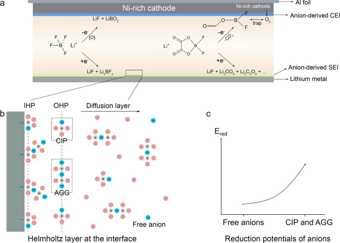
To interpret the contradiction and elucidate the origin of performance improvement by the LiPF6:LiDFOB dual-salt method, the graphite anodes of the three cycled full cells were sent for SEM-EDS (Figure 4a–l) and XPS characterizations (Figure 4m–x). The EDS elemental contents reflect the decomposition degree of electrolytes, and XPS could be used to analyze the specific decomposition substances and proportions. SEM images show that there are cracks on the graphite anode surface cycled with the two LiPF6 single-salt electrolytes (Figure 4a,b,e,f), while a smooth and compact surface is observed for the graphite anode cycled with the LiPF6:LiDFOB dual-salt electrolyte (LiPF6:LiDFOB:TMP:FEMC = 0.5:0.5:2.5:5.5, Figure 4i,j). The contrast in EDS is more obvious. The graphite anode surface cycled with the two LiPF6 single-salt electrolytes exhibits high F and P contents (Figure 4c,d,g,h), demonstrating the serious decomposition of the electrolytes. Comparatively, the electrolyte with low TMP proportion (LiPF6:TMP:FEMC = 1:1.6:6.4) shows lower F and P contents (Figure 4g,h), indicating that modulation of the Li+ solvation structure could alleviate the reduction of the electrolyte. In sharp contrast, however, the considerably low F and P contents of the dual-salt electrolyte (LiPF6:LiDFOB:TMP:FEMC = 0.5:0.5:2.5:5.5, Figure 4k,l) demonstrate the great inhibition of the electrolyte reduction by the favorable SEI (Figures 4i,j).

The XPS spectra are described in Figure 4m–x. In the C 1s spectra, the CF3 and C═O peaks are from the decomposition of FEMC, the C–O peak is from FEMC or TMP, and the C–C peak is from the graphite. (36) The CF3, C–O, and C═O peaks of the LiPF6:TMP:FEMC = 1:2.5:5.5 electrolyte (Figure 4m) are quite high, which indicates serious decomposition of the electrolyte and is in agreement with the high F and P contents (Figure 4c,d). The P–O peak of the O 1s and P 2p spectra is from the decomposition of TMP. (37) The P–O peak is observed for the two LiPF6 single-salt electrolytes (Figures 4n,p,r,t), but the intensity is lower for the LiPF6:TMP:FEMC = 1:1.6:6.4 electrolyte, suggesting the TMP decomposition could be alleviated by modulation of the Li+ solvation structure. In sharp contrast, the P–O peak is almost negligible for the dual-salt electrolyte (LiPF6:LiDFOB:TMP:FEMC = 0.5:0.5:2.5:5.5, Figure 4v,x), demonstrating the significant inhibition of TMP decomposition and in accordance with the low P content in EDS (Figure 4l). In the F 1s spectra (Figure 4o,s,w), the LiF and C–F peaks are, respectively, from the Li salt and FEMC, (20,21) and the B–F peak suggests the participation of LiDFOB in the SEI formation (Figure 4w). (36,37)
The conclusion is based on the analysis of the battery performance, Li+ solvation structure, and interphase. Modulation of the Li+ solvation structure could alleviate the electrolyte decomposition via boosting the reduction tolerance in thermodynamics (higher LUMO energy level), while for the LiPF6:LiDFOB dual-salt electrolyte, the decomposition of TMP is kinetically inhibited by the compact interphase, although the reduction tolerance is affected by DFOB– (lower LUMO energy level). These results also demonstrate the equal importance of Li+ solvation structure and interphase. The Li+ solvation structure is the indication of reduction tendency in thermodynamics, and a perfect interphase would slow down the electrolyte decomposition in kinetics (Figure 5). It is noteworthy that the quality of SEI could not be always fully reflected from the Li/Gr half cells because of the excessive Li resources contributed from the Li metal anode. While for the full cell, even a tiny defect would cause a difference in the cycling performance.

Then the cycling performances of the Li/Gr half cells using the pure TMP (LiPF6:TMP = 1:8) and pure FEMC (LiPF6:FEMC = 1:8) electrolytes could also be explained. The LiPF6:TMP = 1:8 electrolyte has a considerably low LUMO energy level (−2.19 eV, (1) in Figure 2a, CN = 3.80) and an inferior reduction tolerance. The incompatibility of the LiPF6:TMP = 1:8 electrolyte with graphite is mainly due to the thermodynamics (Figure S4a,b). While for the pure FEMC electrolyte (LiPF6:FEMC = 1:8), its SEI is unfavorable to prevent decomposition, in spite of the high reduction tolerance of its Li+ solvation structure (LUMO of 2.53 eV, (4) in Figure 2a, CN = 1.93). The incompatibility of the LiPF6:FEMC = 1:8 electrolyte with graphite is mainly due to the kinetics (Figure S4c,d). The SEM-EDS of the cycled graphite electrodes reveals the exfoliation of graphite in LiPF6:TMP = 1:8 (Figure S12a,c) and thick decomposition products from LiPF6:FEMC = 1:8 (Figure S12b,d). The high F content demonstrates the serious decomposition of the electrolyte (Figure S12f,h). Further XPS results indicate the decomposition products are mainly from TMP and LiPF6:FEMC, respectively, for the LiPF6:TMP = 1:8 and LiPF6:FEMC = 1:8 electrolytes (detailed analysis shown in Figure S13).
The different origins of the capacity decay between these two electrolytes could be demonstrated further by the following electrochemical tests. The Li/Gr half cells were first cycled using the commercial electrolyte (LiPF6 (1 mol L–1) in EC/EMC with 5 wt % FEC) for three cycles to construct a good SEI, and then the cycled graphite electrodes were used for pure TMP (LiPF6:TMP = 1:8) or pure FEMC (LiPF6:FEMC = 1:8) electrolytes (Figure S14a–d). The LiPF6:TMP = 1:8 electrolyte failed also (Figure S14a,b), while the LiPF6:FEMC = 1:8 electrolyte provides a reversible capacity of 318 mAh g–1 with an acceptable cycling stability (Figure S14c,d). The high reduction tendency of the LiPF6:TMP = 1:8 electrolyte could hardly be resolved by the SEI, while a good SEI partially overcomes the weak point of the LiPF6:FEMC = 1:8 electrolyte. Moreover, FEC (5 wt %) was also added to these two electrolytes (Figure S14e–h). A moderate capacity (∼200 mAh g–1) is provided by the Li/Gr half cell using the electrolyte of LiPF6:TMP = 1:8 + 5 wt % FEC, but the cell faded with the run out of FEC (Figure S14e,f). In contrast, the Li/Gr cell using the electrolyte of LiPF6:FEMC = 1:8 + 5 wt % FEC exhibits a high reversible capacity (355 mAh g–1) as well as a good cycling stability over 80 cycles (Figure S14g,h).
The contrast of pure TMP and pure FEMC electrolytes suggests the priority of elucidating the origin of incompatibility between the electrolyte and graphite anode to the performance optimization. The stable cycling of Li/Gr could be achieved by interphase regulation if the electrolyte has a high reduction tolerance (such like the pure FEMC electrolyte). However, it is more important to modulate the Li+ solvation structures for the electrolytes with a low reduction tolerance (such as the pure TMP electrolyte). Interestingly, the SEI properties of TMP are not as disappointing as generally recognized. Despite the high LUMO energy levels of the pure FEMC electrolyte (LiPF6:FEMC = 1:8, 2.53 eV, (4) in Figure 2a) and the electrolytes containing small amounts of TMP (2.30, 2.75, and 2.79 eV, (6), (7), and (8) in Figure 2d), the Li/Gr half cells using these two types of electrolytes show sharp contrast in the performance (Figure 1a,b and Figure S4c,d). It is deduced that the SEI formed by small amounts of TMP is better than that formed by pure FEMC electrolyte, although a high proportion of TMP would largely reduce the thermodynamic reduction tolerance.
3.4. A Comprehensive Optimization with Thermodynamics and Kinetics
For the optimized solvent ratio (TMP:FEMC = 1.6:6.4), single-salt (LiPF6 and LiDFOB) and dual-salt (LiPF6:LiDFOB) electrolytes were compared, and the results are described in Figure 6. All of the three electrolytes exhibit high performance for the Li/Gr half cells (Figure 6a and Figure S15) and show no prominent difference in the Li/NCM811 half cells (Figure 6b and Figure S16). However, an obvious discrepancy is observed in the Gr/NCM811 full cells (Figure 6c and Figure S17). The dual-salt electrolyte shows the best cycling stability (175 mAh g–1, 92.9% in Figure 6c), indicating LiDFOB is not the better one. Moreover, the dual-salt strategy is also advantageous in the rate capability over single-salt electrolytes (Figure 6d), as LiPF6 and LiDFOB have a rational division of functions (SEI-formation and Li+ conducting).

As illustrated in Figure 3, replacing part or all of PF6– by DFOB– for the Li+ solvation structures containing two anions would lead to a significant decrease of the LUMO energy level from ∼2.5 eV to ∼1.0 eV. On the other hand, it would also lead to a significant increase of HOMO from −6 eV to −4.5 eV ((3) in Figure S3, (9) and (12) in Figure S11). Hence, introduction of DFOB– would cause a decrease of both of the reduction and oxidation tolerance in thermodynamics. However, the LiPF6 single-salt electrolyte (LiPF6:TMP:FEMC = 1.0:1.6:6.4) shows the worst performance compared with the LiDFOB-containing electrolytes (Figure 6c).
The cathode electrolyte interphase (CEI) of these three Gr/NCM811 full cells was characterized with SEM-EDS and XPS after 30 cycles (Figure S18). (12,38) EDS shows that there is no sharp difference in the F and P element fractions among these three NCM811 cathodes (Figure S18a–p), and further XPS exhibits that the CEI components are almost the same (Figure S18q–af). These results suggest CEI is not the predominant factor of the Gr/NCM811 full cell (the upper voltage is only 4.3 V). The SEI characterization results are compared in Figure 7. The SEM-EDS reveals the sharp difference of the graphite surface (Figure 7a–l). The SEI of the LiDFOB single-salt electrolyte is coarse and contains plenty of particles (Figure 7e,f), in sharp contrast to the SEI of the LiPF6 single-salt electrolyte (Figure 7a,b). While for the LiPF6:LiDFOB dual-salt electrolyte, the SEI is smooth and compact (Figure 7i,j), and the F and P contents (Figure 7k,l) are lower than those of the LiPF6 (Figure 7c,d) and LiDFOB single-salt electrolytes (Figure 7g,h), indicating the lowest decomposition degree of the LiPF6:LiDFOB:TMP:FEMC = 0.5:0.5:1.6:6.4 electrolyte at the graphite anode. The EDS element proportions of CEI (Figure S18a–p) and SEI (Figure 7a–l) confirm that SEI is the predominant factor of the cell performances shown in Figure 6c. The XPS spectra of the SEI are described in Figure 7m–x. The low intensity of the C–C peak suggests the good protection of graphite by the compact SEI of the LiPF6:LiDFOB dual-salt electrolyte (Figure 7u). Decomposition of TMP is signified by the P–O peaks for the two single-salt electrolytes (Figure 7n,r,p,t). The absence of P–O peak confirms prevention of the TMP decomposition by the LiPF6:LiDFOB dual-salt electrolyte (Figure 7v,x). Difference is also observed in the F 1s and P 2p spectra of the LiDFOB-containing electrolytes (Figures 7s,t,w,x), in which the stronger B–F peak (Figure 7w) and the emerge of POxFy peak (Figure 7x) of the LiPF6:LiDFOB dual-salt electrolyte suggest the reaction at the graphite is a synergistic consequence of the two salts. (39)

Nonflammability was confirmed for the three electrolytes of Figure 6, in contrast to the highly flammable commercial electrolyte (Figure S19). Meanwhile, the high-voltage performance is also a highlight of the present electrolytes (Figure S20). The Gr/NCM811 full cell using the LiPF6:LiDFOB dual-salt electrolyte exhibits a 100-cycle capacity retention rate of 76.9% with an upper voltage of 4.6 V (Figure S20d, 43% for the commercial electrolyte, Figure S20f). Moreover, the low-temperature cycling (−40 °C) could also be carried out because of the low viscosity of FEMC (Figure S21).
4. Conclusions
In summary, the present study develops nonflammable LIB electrolytes with the total mole ratio between Li salts and solvents of 1:8. The Li salts are LiPF6 and/or LiDFOB and the solvents are binary TMP:FEMC. For the LiPF6 single-salt electrolyte, the solvent molecules and anions in the Li+ solvation structure decrease and increase, respectively, with the decreasing mole ratio of TMP:FEMC. Correspondingly, the reduction tolerance increases with the boosting LUMO energy level, leading to a better cycling of the Li/Gr half cell. Neither the pure TMP (LiPF6:TMP = 1:8) nor pure FEMC (LiPF6:FEMC = 1:8) electrolytes could afford the cycling of Li/Gr half cells. The former is due to thermodynamics (low reduction tolerance) while the later is due to kinetics (SEI could not inhibit the side reaction). For the Li+ solvation structures containing two anions, replacing part or all of PF6– by DFOB– would lead to a significant decrease of the reduction tolerance (decreasing LUMO energy level). However, for the fixed solvent mole ratios (TMP:FEMC = 2.5:5.5 or 1.6:6.4), the LiPF6:LiDFOB dual-salt electrolytes provide a better cycling performance for both of Li/Gr half cell and Gr/NCM811 full cell. The LiPF6:LiDFOB dual-salt electrolyte forms a better SEI to inhibit the side reaction at the graphite anode, in spite of the lower reduction tolerance than the LiPF6 single-salt electrolyte. The Li+ solvation structure is the indication of reduction tendency in thermodynamics, and a perfect interphase would slow down the electrolyte decomposition in kinetics. Binary salt electrolytes can be used in the electrolyte design, one to improve the reduction tolerance of the solvation structure (thermodynamics), and the other to ensure conductivity and good interphase (kinetics). It is revealed in the present study that Li+ solvation structure and interphase are respectively the thermodynamic and kinetic factors of the side reactions at the electrolyte/electrolyte interphase, which should be considered comprehensively in the design of the LIB electrolytes.
【Article link】
https://doi.org/10.1021/acsaem.2c03065