Deyang Yu
Department of Chemistry and Macromolecules Innovation Institute, Virginia Tech, Blacksburg, Virginia 24061, United States
More by Deyang Yu
https://orcid.org/0000-0003-0587-1211,
Linqin Mu, Xu Feng, Feng Lin, and Louis A. Madsen
Cite this: ACS Appl. Energy Mater. 2022, 5, 10, 12531–12537
Publication Date:September 22, 2022
Abstract
Polymer binders are important components of most battery electrodes, ensuring high performance and long-term durability. Increasing demand for lithium-ion batteries in the automotive, stationary power, and portable electronics industries calls for a greener binder to replace poly(vinylidene difluoride) (PVDF). We evaluate the performance of aqueous solution-processed electrodes prepared with a rigid-rod polymer binder, poly(2,2′-disulfonyl-4,4′-benzidine terephthalamide) (PBDT). The polyamide backbone and double-helical configuration of PBDT give rise to its mechanical strength and rigidity, and its functional nature (H-bonding amides and sulfonates) can provide specific binding with electrode particles. LiFePO4 electrodes prepared with 3 wt % PBDT show mechanical integrity and cycling stability, achieving over 1000 cycles at 4C rate with negligible capacity decay. These electrodes demonstrate comparable rate performance with their PVDF counterparts while eliminating fluorine from the electrode as well as the organic solvents needed for processing. This study reveals that PBDT holds great potential as a binder for advanced sustainable batteries.
Introduction
Lithium-ion batteries (LIBs) are important energy storage devices for greener use of energy, and they have found wide applications ranging from portable electronics, to electric vehicles, to grid energy storage. (1,2) Extensive efforts have been devoted to developing novel active materials, electrolytes, and additives to enhance their energy density, cycle life, and safety. (3−5) Polymer binders for electrodes have also received increasing attention due to the recognition of their critical roles in the cycling stability and rate capability of LIBs. (6−12) The primary role of a binder is to firmly hold the active material and electronically conductive particles together in the electrode and adhere them tightly to the current collector, thus ensuring facile and uniform electron conduction through the entire electrode during cell cycling. In addition, the binder in general should be both chemically and electrochemically stable and should possess high thermal stability, good ionic conductivity, high mechanical properties, and sufficient dispersion capability. (13) Although the requirements of the binder can vary significantly according to the electrode active material, poly(vinylidene difluoride) (PVDF) remains the most commonly used binder in commercial LIBs. However, PVDF requires a toxic and volatile organic solvent, N-methyl pyrrolidone (NMP) to dissolve it during the electrode slurry preparation. With the rapid increase in the demand for LIBs, both the use of NMP in electrode manufacturing and the disposal of the fluorine-containing PVDF at the end of battery life have raised significant environmental concerns. (14) Additionally, it is energy-consuming to recycle NMP during the electrode drying process. PVDF also suffers from a high degree of swelling in organic electrolytes, which can potentially lead to disconnection of active particles during cell cycling and thus cause performance decay. (15,16) As a consequence, aqueous solution-based, environmentally benign, and high-performance binders are highly desired for sustainable and lower cost batteries.
Many alternative binders that are aqueous-processable have been studied, including carboxymethyl cellulose (CMC), (8,17,18) poly(acrylic acid) (PAA), (19−21) poly(vinyl alcohol) (PVA), (22,23) alginate, (6) and gum Arabic. (24) The cohesion mechanism of such binders is generally described as mechanical interlocking and/or interfacial interactions. (13) Mechanical interlocking refers to the penetration of the binder solution into the surface and pores of the active material and conductive particles during the slurry preparation followed by the hardening/drying of the electrode slurry. (13) Interfacial interactions between the polymer binder and the other electrode components include van der Waals forces, hydrogen bonds, ion–dipole interactions, ion–ion interactions, and covalent bonds. (13,25) Predominant binding interactions are typically formed between the polar functional groups of the binder and the other electrode components. (25) For binders containing carboxylic acid groups, the hydrogen bonds formed between −COO– and active materials are widely considered as the main source of binding interactions. (6,21,26)
Achieving high binding strength with low binder content leads to high energy density for LIBs because the binder is generally not electrochemically active. Using binders with more densely populated functional groups can efficiently increase the binding strength and thus electrode performance. Si anodes prepared with sodium alginate as the binder, compared to other binders such as PVDF and CMC, demonstrate greatly improved cycling stability due to the high concentration and uniform distribution of the carboxylic groups in sodium alginate. (6) Bulk mechanical properties, such as tensile modulus (rigidity) and tensile strength, of the binder also critically affect the binding strength. (13,24) Compared to random coil-shaped soft-segmented polymers with the same contour length, rigid polymers have a more linear and stretched conformation in solution. Such stretched conformation can potentially increase the number of binding sites on the polymer chains and thus more efficiently utilize the functional groups. In addition, rigid binders can lead to a high viscosity of the electrode casting slurry at low shear rates, which can aid in preventing electrode particles from settling during the slurry drying process. At the same time, alignment of rigid polymer chains under flow can lead to shear-thinning of the slurry, thereby allowing facile mixing of all electrode components. (17)
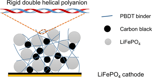
Poly(2,2′-disulfonyl-4,4′-benzidine terephthalamide) (PBDT) is a highly rigid (mesogenic) polyamide with two sulfonate groups and two amide groups per repeat unit, as shown in Figure 1. These functional groups can lead to strong ion–ion and ion–dipole interactions as well as hydrogen bonds between PBDT and electrode materials. In aqueous solution, PBDT chains form a double helical structure, which further increases the rigidity and the number density of exposed functional groups along the polymer chains. (27) Young’s modulus and tensile strength of neat PBDT are 15 GPa and 190 MPa, respectively. (28) The highly charged PBDT also does not swell in organic carbonate electrolytes. These properties endow PBDT with great potential as an advanced electrode binder. Previously, we have been making solid electrolytes by combing PBDT with various ionic liquids and alkali metal salts. (29−32) Here, we evaluate the performance of PBDT as a polymer binder for LiFePO4 electrodes prepared via aqueous solution processing. These electrodes demonstrate good binding and mechanical integrity and exhibit excellent cycling stability over 1000 cycles at 4C rate.

Experimental Section
Electrode Preparation
The 3:10:87 (by wt %) PBDT-carbon-LFP electrode was prepared through the following procedures. PBDT (14.9 mg) was dissolved in 1.10 g of H2O at room temperature. Carbon black (49.9 mg) and 435 mg of LiFePO4 were premixed in an agate mortar. Then, the mixture of carbon black and LiFePO4 was added to the aqueous solution of PBDT and mixed using a SpeedMixer (FlackTek, DAC 150.1 FVZ-K) at 1500 rpm for 8 min. The slurry was then cast onto a carbon-coated aluminum substrate using a doctor blade and pre-dried at 60 °C for 2 h. The electrode was then further dried under vacuum at 100 °C overnight. The 3:10:87 (by wt %) PVDF-carbon-LFP electrode was prepared in a similar way except NMP was used as the solvent. The mass ratio of each component in the electrodes is shown in Table S1.
Electrochemical Measurements
The prepared electrodes were punched into disks with a diameter of 10 mm. The mass loading of LiFePO4 in both 3% PBDT-LFP and 3% PVDF-LFP electrode disks ranges from 3.2 to 3.9 mg/cm2. To evaluate the cycling performance of the electrodes, CR2032 coin cells were assembled in an Ar-filled glovebox using lithium metal as the anode and Whatman glass fiber as the separator with a MTI MSK-160E crimper. Coin cell cycling tests were conducted on a Neware (CT-4008 T) battery tester and a LAND (CT2001A) battery tester. The electrochemical impedance spectrum was recorded using a BioLogic SP-200 instrument as previously reported. (31)
Other Characterizations
Scanning electron microscopy (SEM) was conducted on a LEO (Zeiss) 1550 field emission SEM, and the acceleration voltage was set to 5.0 kV. X-ray photoelectron spectroscopy (XPS) analysis was measured on a PHI VersaProbe III instrument.
Results and Discussion
LiFePO4 is a model candidate cathode material for evaluating aqueous-processed binders. (14) Thus, we can prepare LiFePO4 electrodes using PBDT as the binder. We also prepare electrodes with PVDF as the binder for comparison. We fix the amount of binders in these electrodes to a low content of 3 wt %. To ensure sufficient electronic conductivity, we incorporate 10 wt % carbon black into both electrodes. Figure 2a,b shows the SEM images of the prepared LiFePO4 electrodes. The surface of the 3% PBDT-LFP electrode shows smaller and fewer particle agglomerations than the 3% PVDF-LFP electrode, which has a surface with some short and narrow cracks. Although PBDT is a very rigid polymer, the 3% PBDT-LFP electrode shows substantial flexibility and can be wrapped around a tube with a 5 mm diameter without cracking or exfoliation of particles from the aluminum substrate (Figure 2a, inset), suggesting easy handleability of the electrode. The dispersion ability of binders in electrodes is critical for their electrochemical performance. (33) SEM and energy-dispersive X-ray spectroscopy (EDS) measurements (Figure S1) show that both PBDT and PVDF are homogeneously distributed in the prepared electrodes. These experimental results demonstrate that PBDT has a good affinity with the electrode particles and that just 3 wt % PBDT enhances the mechanical integrity of the electrode and provides sufficient binding strength among electrode particles.

To further evaluate the binding performance of PBDT compared to PVDF, we conduct tape peeling tests (Figure 2c,d). We adhere the electrodes to a tape and then peel them off. For the 3% PVDF-LFP electrode, the LiFePO4 and carbon black particles peel off easily and the carbon coating layer on the aluminum substrate remains essentially intact. This indicates weak binding between the carbon coating layer and the electrode particles. When using PBDT as the binder, we need a higher force to peel the electrode off as evidenced by curling of the current collector (carbon-coated aluminum) after the test. Some of the carbon particles coated on the aluminum also peels off during the test, leading to exposure of the metallic luster of the aluminum. This indicates that PBDT endows higher binding strength between the electrode particles and the current collector. Combined with the poor solubility of PBDT in organic carbonate solvents, we anticipate that the 3% PBDT-LFP electrode can extend cycling stability.
We next examine electrochemical performance of the LiFePO4 electrodes using lithium metal as the anode and 1 M LiBOB (lithium bis(oxalato)borate) in a EC-PC (1:1 volume ratio) mixture as the electrolyte due to its high thermal stability. (34) When cycling the cells at 0.2C rate (where 1C is defined as the rate to completely charge or discharge the cell in 1 h), the specific discharge capacity of 3% PBDT-LFP approximates that of the 3% PVDF-LFP, and both reach over 150 mAh/g at 22 °C after a few initial cycles (Figure 3a). The specific capacity decreases with the cycling rate. At 22 °C and 10C rate, the specific discharge capacities of 3% PVDF-LFP and 3% PBDT-LFP are 86 and 73 mAh/g, respectively. We attribute the slightly larger capacity decay of 3% PBDT-LFP when increasing C rate to the low swelling degree of PBDT in the electrolyte. It is likely that, at the molecular scale of PBDT (∼ 1 nm), the distribution of PBDT on the surface of the LiFePO4 particle surface is not very homogeneous, i.e., some regions of the LiFePO4 surface may be covered by a thicker PBDT layer while other regions are covered by a thinner PBDT layer. The low swelling degree of PBDT could potentially cause an uneven lithiation/delithiation rate of LiFePO4 at high C rate. The regions covered by a thicker PBDT layer have a lower lithiation/delithiation speed due to the increased Li+ transport resistance from the bulk electrolyte to the LiFePO4 particle surface. However, the specific capacities of these two types of electrodes are different by only ∼10% even at 10C rate, suggesting that the resistance caused by PBDT is not substantial. We note that the overpotentials of these cells are almost identical as revealed from the voltage profiles of these cells during cycling (Figure S2). It is also worth noting that the capacity loss caused by fast charge and discharge is reversible. When slowed to 1C rate, we observe that the specific discharge capacity fully recovers to its original value at this rate, and the cell stably runs for 200 cycles without any noticeable capacity decay.

When cycling the cells at 60 °C and 0.2C rate (Figure 3b), both 3% PBDT-LFP and 3% PVDF-LFP demonstrate a specific discharge capacity of 160 mAh/g. This high (near-theoretical) capacity at low C rate suggests a high charge utilization efficiency of LiFePO4 particles in the entire electrode. The specific capacity of these electrodes remains very close to each other when increasing the cycling rate up to 10C. This indicates that the ion transport between the bulk electrolyte and the LiFePO4 particle surface does not limit cell performance at 60 °C. Furthermore, the specific discharge capacity of 3% PBDT-LFP and 3% PVDF-LFP is as high as 140 mAh/g at 10C rate. When the cycling is slowed to 1C rate, both electrodes show essentially full capacity recovery capability. Overall, the rate performance of the LiFePO4 electrode prepared with 3 wt % PBDT as the binder is comparable to that prepared with PVDF as the binder, except for the slightly inferior capacity at high cycling rates and room temperature.
To further investigate the long-term cycling stability of these two types of electrodes, we cycled cells at 4C rate for 1000 cycles at 22 °C following five initial cycles at 0.2C (Figure 3c). We can see that, as discussed above, the 3% PVDF-LFP electrodes have slightly higher (5–8%) specific capacity at 4C rate than the 3% PBDT-LFP. However, we observe a notable capacity decay, from 127 to 120 mAh/g, for the 3% PVDF-LFP electrodes after 560–800 cycles, while the capacity of 3% PBDT-LFP remains essentially constant for 1000 cycles. Further experiments show that 3% PBDT-LFP electrodes start to show slight capacity decay only after 1100–1500 cycles, and the specific discharge capacity after 2000 cycles is still as high as 107 mAh/g on average with only 10% capacity loss at 4C rate (Figure S3). Thus, the LiFePO4 electrode prepared with PBDT as the binder has better cycling stability over PVDF. This lack of obvious performance decay over long-term cycling makes PBDT a promising binder material for enabling lithium-ion batteries for applications such as electric vehicles and grid storage.
We use SEM to examine the morphology of the electrode surface after 1000 cycles at 4C rate. As shown in Figure 4, the surface of 3% PBDT-LFP remains intact, while the length of the cracks on 3% PVDF-LFP grows after cycling. Very interestingly, we find that the surface of 3% PBDT-LFP becomes covered with a thin layer of material that we do not observe on the surface of 3% PVDF-LFP. We further compare X-ray photoelectron spectroscopy (XPS) results for the pristine 3% PBDT-LFP and for the same electrode after 1000 cycles to get a better understanding of the origin of this in situ-formed thin artificial layer (Figure S5). Before cycling, the electrode surface shows obvious N and S signals attributed to the −CONH– and −SO3– groups from the PBDT binder. After cycling, we observe no obvious N or S signals, indicating that this surface layer does not arise from PBDT itself. Thus, it appears likely that this artificial layer mainly consists of side reaction products from the electrolyte.

To better understand interfacial phenomena before and after cycling for both PBDT- and PVDF-based electrodes, we also present a deeper analysis of C 1s and O 1s XPS spectra (Figure 5). The C 1s and O 1s spectra of pristine 3% PBDT-LFP and 3% PVDF-LFP electrodes are dominated by carbon black and LiFePO4 signals. The C═O species on the surface of carbon black also shows a minor peak at 533.1 eV in the O 1s spectra. (35) After cell cycling, the C 1s spectra of both types of electrodes show dominant O═C─O (289.5 eV) and C═O (287.4 eV) species. (36) Accordingly, the O 1s spectra of both 3% PBDT-LFP and 3% PVDF-LFP show two strong peaks at 532.5 and 533.7 eV, attributing to C═O and C–O, respectively. These similarities between 3% PBDT-LFP and 3% PVDF-LFP after cell cycling strongly indicate that the main component of the artificial layer observed in Figure 4b is the common cathode electrolyte interphase (CEI) originating from oxidation of the electrolyte on the cathode surface. Conceivably, PBDT and the CEI components are somewhat less compatible with each other, and the high binding strength and low swelling degree of PBDT cause the CEI to accumulate on the electrode surface rather than on the surface of active LFP particles uniformly. However, this does not substantially affect performance for PBDT-LFP over 2000 cycles at 4C.

Conclusions
We evaluated the viability of using the highly rigid and charged PBDT polymer as an electrode binder. The LiFePO4 electrode prepared with 3 wt % PBDT, processed entirely from aqueous solution, shows comparable but slightly inferior high C rate capacity at room temperature compared with the traditional fluoropolymer binder PVDF. At 60 °C, the two electrodes exhibit the same rate performance. Long-term cycling results at 4C rate demonstrate that the LiFePO4 electrode with the PBDT binder has better stability as compared to PVDF. In contrast to binders extracted or adapted from natural sources, we can synthesize the PBDT polymer from commercial monomers via a simple one-step reaction, the details of which are published. (37−39) The chemical structure and physical properties of PBDT are well characterized and can be further tuned to optimize for specific applications. This study demonstrates that PBDT holds great potential as a straightforward and robust binder material in commercial battery applications.
【Article link】
https://doi.org/10.1021/acsaem.2c02173

