Bin LiangBin Liang
Myj Chemical Company Limited, Puyang, Henan 457000, China
More by Bin Liang, Fangyuan Cheng, Xiaoyu Ge, Xuejun Tan, Chun Fang, and Jiantao Han
Cite this: ACS Appl. Energy Mater. 2022, 5, 5, 5867–5874
Publication Date:May 3, 2022
Abstract
The Ni-rich LiNixMnyCozO2 (x + y + z = 1, x > 0.5, Ni-rich NMC) materials are one of the most potential cathodes for high energy density lithium-ion batteries (LIBs) due to their high specific capacity and relatively low cost. However, performances of LIBs with the Ni-rich NCM cathode below 0 °C are restricted by low ion conductivity of the electrolyte and a slow ion diffusion rate at the electrode–electrolyte interphase. Here, γ-butyrolactone (GBL) with a low melting point and high ion conductivity is used to partially replace ethylene carbonate, which is conducive to lower the freezing point and increase the low-temperature ionic conductivity of the electrolyte, and the addition of GBL improves the dissolution of lithium difluoro(oxalato)borate (LiDFOB) in a traditional carbonate solvent. Instead of lithium hexafluorophosphate (LiPF6), LiDFOB can form a F-, B-, and O-rich interfacial phase at the Ni-rich NCM cathode, suppressing the fatal interface reaction and reducing the interface impedance. As a result, the electrolyte using GBL as the cosolvent and LiDFOB as the lithium salt can significantly improve the specific discharge capacity and cycling stability of LiNi0.8Co0.1Mn0.1O2/Li cells at 0 °C and −30 °C. At 0 °C, the LiNi0.8Co0.1Mn0.1O2/Li cells have a discharge specific capacity of 160 mA h g–1 and a capacity retention rate of 99% over 100 cycles. They deliver a decent capacity at −30 °C. This rational design of an electrolyte via optimizing the combination of a solvent and a lithium salt has been confirmed to be a low cost but rather an effective method to improve the low-temperature performances of LIBs.
Introduction
Lithium-ion batteries (LIBs) have been widely used in mobile electronic devices, electric vehicles (EVs), power grid storage, and space exploration due to their high energy density and long cycle life, which have promoted the great progress of the world in the past three decades. (1,2) However, temperature is the key factor to determine the performance of lithium-ion batteries. The energy and power of lithium-ion batteries are seriously attenuated below 0 °C. When the temperature drops to −30 °C, commercial LIBs can only provide 10% of their room-temperature capacity. (3,4) In addition to the attenuation of performance, charging of LIBs at low temperature will cause a serious polarization, resulting in lithium deposition and dendritic growth, which will bring irreversible adverse impacts and great potential safety risks to the battery. (5) The research and development of high-performance low-temperature batteries can not only break through the application limitations of lithium-ion batteries in extremely cold environments (high latitudes and aerospace applications) but also greatly promote the development of electric vehicles. The reasons for the low-temperature performance degradation of lithium-ion batteries are as follows: (6,7) first, the diffusion rate of Li+ in the positive and negative electrodes is limited at low temperatures. Second, the viscosity of the lithium-ion battery electrolyte increases at low temperature due to the high melting point (e.g., 36–38 °C) of the main solvent in the electrolyte. (8) It will even cause the electrolyte to solidify at low temperature, which is very fatal to the batteries. (9) Moreover, the migration of ions is obstructed at the electrode–electrolyte interface owing to the slow kinetics at low temperature, which ultimately leads to large polarization during charging and discharging processes and causes the battery decay.
To address the problems of high electrolyte viscosity, low ion conductivity, and slow ion transmission at the electrode–electrolyte interface at low temperatures, various strategies have been proposed. Tron et al. (10) have designed an antifreeze additive of ethylene glycol for aqueous electrolyte solutions and used to improve the low-temperature performance of aqueous rechargeable lithium-ion batteries. Jones et al. (11) have found that 0.1 M LiFSI is advantageous to low-temperature charging. McDowell (12) has found that the use of cyclic carbonates, ethers, and fluoroethylene carbonates (FEC) can improve the coulombic efficiency and cycling performance of lithium metal batteries at low temperatures (−60 °C). Among them, FEC facilitates the formation of a LiF-rich interface film. This results in temperature-dependent changes in the chemistry and structure of the interfacial phase. Guo et al. (13) have designed a novel strategy that a low impedance interface at the anode is framed by using dimethyl sulfite as an electrolyte additive. The cycling performance tests prove that the interfacial film formed at a low temperature of −20 °C can significantly improve the stability of the LiNi0.5Co0.2Mn0.3O2/graphite full battery. Cui et al. (14) used lithium trifluoro(perfluoro-tert-butoxy) borate (LiTFPFB) and lithium bis(trifluoromethanesulfonyl)imide (LiTFSI) as double salts, lithium difluorophosphate (LiPO2F2) as the additive, and carbonates with a low melting point and a high boiling point as solvents, and the prepared electrolyte significantly improved the cycling performance of the LiNi0.5Mn0.3Co0.2O2/Li battery at −20 °C. In the above strategies, improving the electrolyte through solvents, lithium salts, or additives can all improve the performances of LIBs at low temperatures, but some of them cannot be used on a large scale due to the high cost. In contrast, using low-cost solvents, lithium salts, and additives to modify and improve traditional electrolytes to optimize low-temperature electrolyte formulations is an effective and convenient strategy to be commercialized.
In this work, low-cost γ-butyrolactone (GBL) with a low melting point (−43.5 °C) and a high dielectric constant was selected to partially replace EC with a high melting point (36–38 °C) to reduce the freezing point and increase ionic conductivity of the electrolyte at low temperature. (15) On the other hand, GBL has high solubility for various lithium salts, and it will broaden the selectivity of lithium salts. (16) Lithium difluoro(oxalato)borate (LiDFOB) with good film-forming properties is selected as the lithium salt, which can form F-, B-, and O-rich interface films on the surface of the electrode, suppress the side reaction, and reduce the interface impedance, which are beneficial to increase the capacity of the battery at low temperatures. The specific discharge capacity and cycling stability of LiNi0.8Co0.1Mn0.1O2/Li cells are greatly enhanced at 0 and −30 °C by modifying the electrolyte. At 0 °C, the LiNi0.8Co0.1Mn0.1O2/Li cells have a specific discharge capacity of 165 mA h g–1 and a capacity retention rate over 99% when cycled 100 times. At –30 °C, the discharge specific capacity is 50 mA h g–1 and circulate 200 times without attenuation. However, the cell cycled in the baseline exhibits low capacity and rather poor cycling stability, and it even cannot reversibly charge and discharge at −30 °C.
Results and Discussion
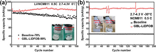
The first discharge capacity at 0 °C of the LiNi0.8Co0.1Mn0.1O2/Li cell with the baseline is 159 mA h g–1 (Figure S1, Supporting Information). As for the cell with GBL-LiDFOB, the first discharge capacity at 0 °C is 167 mA h g–1. The higher discharge specific capacity obtained in GBL-LiDFOB may be due to the higher ion conductivity of the electrolyte at 0 °C. More electrochemical performance data at 0 °C are shown in Figure 1a–c. The state of different electrolytes after placed at 0 °C for 24 h is illustrated in Figure 1a. It can be seen that the GBL-LiDFOB electrolyte is still clear and transparent, while the baseline electrolyte has become turbid, which may be caused by the higher freezing point. Figure 1a reveals the cycling performance of the cell in different electrolytes at 0 °C. The cell is activated at 0.2 C during the first cycle, and the specific discharge curves are shown in Figure S1. After that, the cells are subjected to a long cycle at 0.5 C rate, and the cell with GBL-LiDFOB shows a capacity of 160–170 mA h g–1. It exhibits an excellent capacity retention rate over 99% when cycled 100 times, while the cell with baseline exhibits only 78%. The corresponding charge–discharge curves are shown in Figure 1b,c. For the first 20 cycles, both cells show the same voltage platform. After 50 cycles, the voltage platform of the cells in the baseline shows an obvious drop. The above results illustrate that the structure of the active material is destroyed and the lithiation and delithiation kinetics are hindered. On the contrary, the voltage platform of the cells with GBL-LiDFOB still stays well.

Figure 1d,e shows the cycling performance of the cell in different electrolytes at −30 °C. The cell is first charged to 4.3 V at 0.2 C rate at 25 °C and then placed in a low temperature box at −30 °C for 5 h before being discharged. Figure 1d shows the first specific discharge capacity curve of the cell in different electrolytes at 0.2 C, and it can be seen that the specific discharge capacity of the cell with GBL-LiDFOB is 156 mA h g–1. In comparison, the specific discharge capacity of the cell cycled in the baseline is only 11 mA h g–1. After that, the long cycling performance test is performed at 0.5 C. As shown in Figure 1e, the cell with GBL-LiDFOB still has a discharge specific capacity of 50 mA h g–1 at −30 °C from the 2nd cycle to 200th cycle, and the capacity does not decrease after 200 cycles. For batteries, charging at low temperatures is more difficult than discharging. The charging and discharging of the second cycle and the subsequent cycles are studied at −30 °C (the first charging at 25 °C), and the charging capacity is lower than that of the first cycle, so the discharge specific capacity after the second cycle is also lower. On the contrary, the cell in the baseline is irreversible. This may be due to the fact that the baseline electrolyte has solidified at −30 °C, resulting in high viscosity and low ionic conductivity. This is also confirmed in Figure 1f. It can be seen that the baseline electrolyte has completely solidified after being placed at −30 °C for 5 h, while the GBL-LiDFOB electrolyte remains in a liquid state. It is well confirmed that GBL-LiDFOB has lower viscosity and higher ionic conductivity at low temperatures, which make the GBL-LiDFOB electrolyte more suitable for cell cycling at low temperatures.
In order to further study the structure evolution of the LiNi0.8Co0.1Mn0.1O2/Li cell at 0 °C, the morphology of the Ni-rich NCM cathode and the Li anode after cycling in different electrolytes and the impedance change during the cycling process were investigated. (17,18) The results are displayed in Figure 2. Figure 2a,b shows the SEM images of the Ni-rich NCM cathode of the cell in different electrolytes cycled 100 times. Some severe breakage of the cathode in the baseline electrolyte can clearly be observed, and the cathode surface is obviously uneven (Figure 2a). In contrast, the morphology evolution of the cathode with GBL-LiDFOB is shown in Figure 2b. The Ni-rich NCM cathode remains mechanically intact after 100 cycles, and it can be observed that the Ni-rich NCM cathode cycled in GBL-LiDFOB shows a smooth and uniform morphology, indicating that the cathode–electrolyte interphase (CEI) may be formed during the circulation process and maintained well. An excellent interfacial film is beneficial to inhibit side reactions, relieve stress accumulation during charging and discharging, and reduce breakage of the cathode particles. We also used a scanning electron microscope to investigate the morphology of the lithium anode of the cell with different electrolytes after 100 cycles at 0 °C, as shown in Figure 2c,d. Generally, the deposited lithium particles at lower temperatures are smaller and sharper, resulting in lower coulombic efficiency (Figure S2, Supporting Information) and worse cycling performance of the cell. (12,17,19)Figure 2c shows the morphology of the lithium anode after cycling in the baseline electrolyte. The surface is obviously uneven, and sharp lithium dendrites are formed. The surface of the lithium anode after cycling in GBL-LiDFOB is relatively uniform and dense, and there are no obvious sharp lithium dendrites (Figure 2d). The above comparison shows that the GBL-LiDFOB electrolyte can also lead to a uniform Li deposition at low temperature.

In order to evaluate the effect of the different electrolytes on cell impedance, an electrochemical impedance spectroscopy (EIS) study was conducted on the LiNi0.8Co0.1Mn0.1O2/Li cell. Figure 2e,f shows the impedance data of fully discharged cells, which include the different electrolytes after different cycles at 0 °C and 0.5 C. All impedance spectra can be well fitted by the equivalent circuit displayed in Figure S3 (Supporting Information), which contains the bulk solution impedance (Rs), interfacial film resistance (Rf), and charge transfer resistance (Rct). (20−22) The bulk solution resistance (Rs) when circulated in different electrolytes with various cycles can be seen in Figure 2e,f, and the specific Rs value is shown in Figure S4 (Supporting Information). It can be seen that when the cycle number is 20, 50, and 100, respectively, the Rs value of the cell with GBL-LiDFOB is always lower than that of the cell with the baseline electrolyte, which shows that electrolyte has an effect on the Rs value, and the cell with GBL-LiDFOB has a smaller Rs value. The semicircle in the impedance spectra corresponds to Rf and Rct . Rf and Rct of the cell with GBL-LiDFOB are significantly lower, which indicates that the interface formed in GBL-LiDFOB is more favorable to Li+ transport. Above all, the GBL-LiDFOB electrolyte is more favorable for the electrochemical performance of the cell at low temperature than the baseline electrolyte.
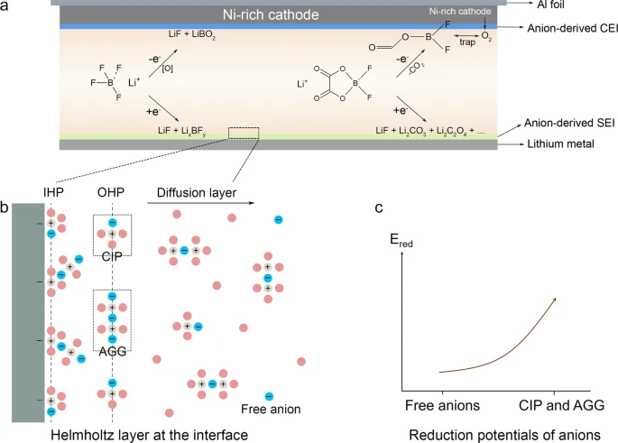
Figure 3 presents the TEM images of the cycled LiNi0.8Co0.1Mn0.1O2 particles at 0 °C. (23) In the baseline electrolyte, the Ni-rich NCM cathode surface is discovered by a uneven interfacial phase, indicating that baseline-constructed CEI is not stable at low temperatures (Figure 3a–c). The byproducts of the CEI reaction accumulate on the Ni-rich NCM cathode, resulting in an increase in interface impedance, which accelerates the degradation of cell capacity at low temperature. Comparatively, a thin and uniform interface film is covered on the surface when GBL-LiDFOB is employed (Figure 3d,e), indicating that the continuous interface side reactions are successfully inhibited by the GBL-LiDFOB-derived CEI. Therefore, compared to the baseline, the structural integrity of Ni-rich NCM is maintained in the presence of GBL-LiDFOB. This can also be verified by the X-ray diffraction (XRD) pattern (Figure S5, Supporting Information) of the N-rich NCM cathode after the cycles. For Ni-rich NCM cathodes, the (003) peak represents the transition-metal layer, and the (104) peak represents the lithium-ion layer and the transition-metal layer. (24) Therefore, the ratio of the two peaks can be used to directly find the degree of lithium–nickel mixing, which is marked as I(103)/I(104), the smaller the ratio, the more serious the lithium–nickel mixing, that is, more NiO is produced. (25,26) Compared to I(103)/I(104) of the Ni-rich NCM cathode after cycling in the baseline, the peak intensity ratio of the cycled cathode with GBL-LiDFOB remains relatively higher. This shows that the harmful rock salt phase caused by lithium-nickel mixing has been suppressed by the CEI generated by GBL-LiDFOB. Figure 3g is a schematic diagram of the corresponding mechanism. The baseline electrolyte-derived CEI on the cathode surface is uneven, incomplete, and thicker that hinder the formation of the required protective layer against the electrolyte. Therefore, the side reactions of Ni4+ at the interface cause severe lithium–nickel mixing, which seriously disrupts the cycle life of the cell. (27,28) On the contrary, the uniform and thin CEI derived from GBL-LiDFOB can protect the active material from side reactions at the electrode–electrolyte interface, so that the structure of cathode can be maintained relatively intact.

The XPS spectra of the cycled LiNi0.8Co0.1Mn0.1O2 cathodes were obtained to further analyze the chemical composition of CEI. Figure 4 shows the C 1s peak, F 1s peak, O 1s peak and B 1s peak, and Ni 2p peak and Li 1s peak. From the XPS spectra of these four different elements, it can be seen that the interface composition after cycling in different electrolytes is significantly different. The C 1s spectra of the Ni-rich NCM cathode cycled in different electrolytes are obviously different in the binding energy range of 288–292 eV. The band near 289 eV corresponds to the −COOR group, which is attributed to the decomposition of GBL. The peaks of F1s reveal that there is less LiF content in the GBL-LiDFOB-derived CEI film. LiF is mainly produced by the decomposition of lithium salt. Therefore, it is speculated that there is less decomposition of lithium salt in GBL-LiDFOB. The B 1s peak also confirms the contribution of LiDFOB to the interface composition. In the O 1s peak, 532 eV corresponds to the O–C/O═C group, which is due to the decomposition of the organic solvent in the electrolyte. The Ni 2p spectra of the outermost surface of the cycled Ni-rich NCM cathode in the baseline electrolyte exhibited a much higher intensity of the Ni2+ peak than that of the cycled cathode in the GBL-LiDFOB electrolyte (Figure 4e), which indicates that the uniform F-, B-, and O-rich CEI could effectively reduce the formation of the electrochemically inactive NiO-like rock -salt structure by suppressing the parasitic reaction between the electrolyte and the Ni-rich NCM cathode surface during the repeated charge–discharge process. In addition, it can be seen from the Li 1s peak in Figure 4f that there are more LiF/C2HOLi at the cathode interface with the baseline. The comparison of C 1s, O 1s, F 1s, Ni 2p, and Li 1s peaks reveals that there is a serious interface reaction in the baseline, resulting in thicker CEI. The peak intensity of this group in the GBL-LiDFOB sample is significantly lower than that in the baseline sample, indicating that the organic components in the GBL-LiDFOB-derived interface are less than in the interface from the baseline electrolyte decomposition. In summary, it shows that both GBL and LiDFOB contribute to CEI, which is beneficial to the formation of organic–inorganic hybrid interfacial phases rich in B, O, and F, which can promote the Li+ transmission. (29,30)

We also measured the cycling performance, electrochemical impedance spectra, and rate performance of the cells in different electrolytes at room temperature (25 °C), and the results are shown in Figure 5. The first charge–discharge curves of cells cycled in different electrolytes are shown in Figure S6 (Supporting Information). There is no significant difference between cells cycled in both electrolytes. Figure 5a shows the cycling performance of the cells in different electrolytes. After 100 cycles, the capacity retention rate of the cell containing GBL-LiDFOB is 94.1%, while that of the cell containing the baseline electrolyte is 90.3%. The corresponding charge–discharge curves of the 10th, 50th, and 100th cycles are shown in Figure 5b,c. The voltage plateau of the cell with the GBL-LiDFOB electrolyte remains slightly better than that of the baseline cell. The electrochemical impedance spectra before and after the cell cycling are shown in Figure 5d,e. The impedance of the cell with GBL-LiDFOB is less than that of the baseline cell, both before and after the cycle. As a result, we tested the rate performance of the LiNi0.8Co0.1Mn0.1O2/Li cells in both electrolytes. As shown in Figure 5f, at low current, the specific discharge capacity of the cell cycled in different electrolytes is similar, but when the rate exceeds 5 C, the specific discharge capacity of the cell with the GBL-LiDFOB electrolyte is much larger than that of the baseline cell. Especially at 20 C, the GBL-LiDFOB-cell still has a specific discharge capacity of 85 mA h g–1, while the specific capacity of the baseline cell drops to 0 mA h g–1. The rate performance corresponds well to the EIS results, which shows that the GBL-LiDFOB electrolyte has a significant improvement in the rate performance at room temperature.

Conclusions
GBL is used as a solvent to partially replace EC, and LiDFOB is used as the main salt to replace LiPF6. The GBL-LiDFOB electrolyte has a lower freezing point and higher Li+ conductivity at low temperatures, which are more favorable for cell capacity at low temperatures. Additionally, GBL and LiDFOB also contribute to the formation of a CEI film, which is conducive to the formation of F-, B-, and O-rich interfacial phases. Compared with the interfacial film formed in the baseline electrolyte, the GBL-LiDFOB-derived interface film is thinner and more uniform, which is more beneficial to Li+ transmission as well as can prevent harmful interface reactions, inhibiting the lithium–nickel mixing to produce an inert rock salt phase. Therefore, at 0 °C, the LiNi0.8Co0.1Mn0.1O2/Li cells with the GBL-LiDFOB electrolyte have a discharge specific capacity of 160 mA h g–1 and a capacity retention rate of 99% over 100 cycles. At −30 °C, the discharge specific capacity is 50 mA h g–1, and the capacity retention rate is close to 100% over 200 cycles. The electrochemical performances at low temperature are significantly improved through GBL and LiDFOB substitution in the electrolyte. This work provides an electrolyte design strategy for the development of low-cost and high-energy batteries based on nickel-rich NCM cathode materials with excellent low-temperature performance.
【Article link】
https://doi.org/10.1021/acsaem.2c00205